20
Assembly
MAN0160 (Rev. 8/19/2005)
Models: M & MT
Install Offset Linkage
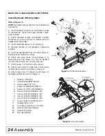
1.
Model M only - Place boom and pivot assembly to
desired position. Align holes at bottom of pivot
assembly and insert tilt lock pin (1) as shown. Rotate
pin to lock into position.
2.
With boom 90 degrees to the blade, place retain-
ing cap (3) on boom as shown in Figure 6.
3.
Install three cap screws (12), lock washers (14),
and flat washers (13) to secure boom to blade assem-
bly.
NOTE:
For model MT, do not install front cap screw,
(12) at this time.
4.
Rotate boom to desired position. Install lock pin
assembly (2) through end of boom and pivot assem-
bly. Secure with safety pin (10).
5.
Insert inner swing link (4) into outer swing link (5).
6.
Attach outer swing link to the A-Frame and insert
clevis pin (15). Secure with cotter pin (11).
7.
Attach inner swing link (4) to the boom and insert
clevis pin (15). Secure with cotter pin (11).
8.
Rotate A-Frame to desired position. Align holes in
inner and outer swing links and insert lock pin (16).
Secure with safety pin (10).
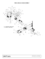
Figure 6
Manual Configuration
NOTE:
For Model
MT
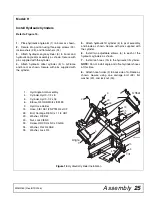
, proceed to page 22 for hydraulic tilt cylinder installation instructions.
16
15
15
14
13
3
12
2
11
11
10
10
5
4
3
2
1
CD5980-2
1.
Tilt lock Pin
2.
Lock Pin Assembly
3.
Retaining Cap
4.
Link, Inner Swing
5.
Link, Outer Swing
10.
Pin, Safety 3/16
11.
Pin, Cotter 1/4 x 1-3/4
12.
Screw, HHCS 3/4 NC x 2-1/4 GR5
13.
Washer, Flat 3/4 SAE
14.
Washer, Lock 3/4
15.
Pin, Clevis 1 x 2-1/2 HT
16.
Pin, Swing Lock


