Assembly
27
MAN0160 (Rev. 8/19/2005)
Install Selector Valve Kit 1004873
(Optional)
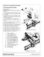
Refer to Figure 19.
NOTE:
Double relief valves must be installed for use
with this option.
1.
Remove hoses on the tractor side of double relief
valves. Two of these hoses will be reused to complete
the selector valve installation.
2.
Remove hose holder (13) and hardware from the
A-Frame if previously installed during angle kit
assembly.
3.
Attach double selector valve (2) to valve mount-
ing bracket (1). Secure with cap screw (26), cap
screw (27), four flat washers (28), and lock nuts (29).
NOTE:
Cap screw (27) is 3-1/2 inches long and used
for attaching hose holder (13) to the top of the selec-
tor valve as shown in Figure 19.
Hose holder can be positioned on either side of the
selector valve, depending on the location of the trac-
tor remote couplers.
4.
Attach selector valve and bracket assembly to the
A-Frame. Secure in place using two carriage bolts
(25), flat washers (28), and lock nuts (29).
5.
Install four adapter fittings (3) in the side ports of
the selector valve (2).
6.
Install four 26” hoses (5) between adapter fittings
(3) in side ports of the selector valve (2) and the relief
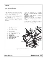
valve (11). See Figure 20 for hose connections.
7.
Install two elbows (4) into the top ports of the
selector valve.
8.
Install two 66” hoses (9) into elbows (4) on the top
of the selector valve.
1.
Bracket, Valve Mounting
2.
Valve, Double Selector
3.
Adapter, 3/4 JICF 1-1/16 ORBM
4.
Elbow, 3/4 JICM 1-1/16 ORBM x 90
5.
Hose, 3/8 26 3/4 JICF 3/4 JICF
9.
Hose, 3/8 66 1/2 NPTM 3/4 JICF
(from Hydraulic Offset Configuration)
11.
Valve, Double Relief 1600 psi
13.
Hyd Hose Holder
(from Hydraulic Angle Kit)
25.
Bolt, Carriage 3/8 NC x 1 GR5
Figure 19
Selector Valve Kit Installation
Figure 20
Selector Valve Hose Connections
26.
Cap Screw, 3/8 NC x 3 GR5
27.
Cap Screw, 3/8 NC x 3-1/2 GR5
28.
Washer, Flat 3/8 Standard
29.
Nut, Lock 3/8 NC
11
25
5
29
26
28
27
28
5
13
29
28
9
3
1
4
2
CD5987
D
C
B
A
C
D
A
B
CD6053-1
Selector Valve
Relief Valves


