background image

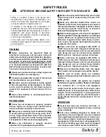
Safety

 5

RD Mower (Rev. 4/28/2006)

„

Always wear relatively tight and belted clothing

to avoid getting caught in moving parts. Wear
sturdy, rough-soled work shoes and protective
equipment for eyes, hair, hands, hearing, and head;
and respirator or filter mask where appropriate.

„

Make sure attachment is properly secured,

adjusted, and in good operating condition.

„

Keep all persons away from operator control

area while performing adjustments, service, or
maintenance.

„

 Make certain all movement of equipment com-

ponents has stopped before approaching for ser-
vice.

„

Never go underneath equipment (lowered to the

ground or raised) unless it is properly blocked and
secured. Never place any part of the body under-
neath equipment or between moveable parts even
when the engine has been turned off. Hydraulic
system leak down, hydraulic system failures,
mechanical failures, or movement of control levers
can cause equipment to drop or rotate unexpect-
edly and cause severe injury or death. Follow Oper-
ator's Manual instructions for working underneath
and blocking requirements or have work done by a
qualified dealer.

„

Frequently check blades. They should be sharp,

free of nicks and cracks, and securely fastened.

„

Do not handle blades with bare hands. Careless

or improper handling may result in serious injury.

„

Your dealer can supply genuine replacement

blades. Substitute blades may not meet original
equipment specifications and may be dangerous.

„

Tighten all bolts, nuts, and screws to torque

chart specifications. Check that all cotter pins are
installed securely to ensure equipment is in a safe
condition before putting unit into service.

„

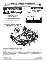
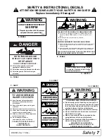
Make sure all safety decals are installed.

Replace if damaged. (See Safety Decals section for
location.)

„

Make sure shields and guards are properly

installed and in good condition. Replace if damaged.

„

Wear gloves when installing belt. Be careful to

prevent fingers from being caught between belt
and pulley.

„

Use care when installing or removing belt from

spring-loaded idler. Springs store energy when
extended and, if released suddenly, can cause per-
sonal injury.

STORAGE

„

Follow manual instructions for storage.

„

Keep children and bystanders away from stor-

age area.

™

SAFETY RULES

ATTENTION! BECOME ALERT! YOUR SAFETY IS INVOLVED!

Summary of Contents for RD6000-2, RD7200-2, RD8400-2

Page 1: ...OPERATOR S MANUAL REAR DISCHARGE MOWERS MAN0180Rev 4 28 2006 Tested Proven Unbeatable RD6000 2 RD7200 2 RD8400 2...

Page 2: ...pecified Observe all safety information in this manual and safety decals on the equipment For service your authorized Woods dealer has trained mechanics genuine Woods service parts and the necessary t...

Page 3: ...8 OWNER SERVICE 14 TROUBLE SHOOTING 18 DEALER SERVICE 20 ASSEMBLY 28 DEALER CHECK LIST 32 PARTS LISTS 33 BOLT TORQUE CHART 41 BOLT SIZE CHART ABBREVIATIONS 42 INDEX 43 PRODUCT WARRANTY 44 REPLACEMENT...

Page 4: ...hielding removed The purpose of this manual is to assist you in operating and maintaining your mower Read it carefully It fur nishes information and instructions that will help you achieve years of de...

Page 5: ...e putting equipment into service Power unit must be equipped with ROPS or ROPS cab and seat belt Keep seat belt securely fastened Falling off power unit can result in death from being run over or crus...

Page 6: ...aintenance follow these steps disengage power to equipment lower the 3 point hitch and all raised components to the ground operate valve levers to release any hydraulic pres sure set parking brake sto...

Page 7: ...ng underneath and blocking requirements or have work done by a qualified dealer Frequently check blades They should be sharp free of nicks and cracks and securely fastened Do not handle blades with ba...

Page 8: ...7 3 Serial Number Plate MODEL NO SERIAL NO Woods Equipment Company Oregon Illinois U S A BE CAREFUL Use a clean damp cloth to clean safety decals Avoid spraying too close to decals when using a pressu...

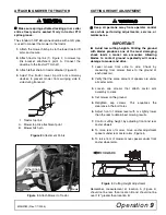
Page 9: ...vy and hands fingers feet and other body parts could be crushed or pinched between tractor and implement Operate tractor controls from tractor seat only Do not stand between tractor and implement when...

Page 10: ...ine groove Operate tractor PTO at the RPM speed stated in Specifications section Before working underneath carefully read Oper ator s Manual instructions disconnect driveline raise mower securely bloc...

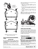
Page 11: ...roduces one of the most damaging shock loads a mower can encounter Allowing blades to contact ground repeatedly will cause damage to mower and drive 1 Level mower from side to side Check by measuring...

Page 12: ...B The pivot tube should be higher than the mounting holes Figure 8 shows the two possible configurations for the RD6000 2 and RD7200 2 front caster arms The inner position allows the outside edge of t...

Page 13: ...ount front casters in the outer position NOTE On model RD8400 2 caster wheel width is not adjustable see tractor operator s manual and adjust tractor wheels to narrower spacing Figure 9 Front Gauge Wh...

Page 14: ...nd clear area of stones branches or other hard objects that might be thrown causing injury or damage Extremely tall material should be cut twice Set mower at a higher cutting height for the first pass...

Page 15: ...ted locking pin or collar slides freely and is seated firmly in trac tor PTO spline groove ___ Make sure the driveline guards and tether chains are in good condition Guards must rotate freely on drive...

Page 16: ...front to rear movement Raise mower completely set tractor brakes turn engine off remove key block tractor wheels front and rear and disconnect mower driveline from tractor The only approved blocking d...

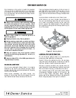
Page 17: ...ure to maintain proper lubrication could result in damage to U joints gearbox and driveshaft 1 Lower mower to ground 2 Apply grease at three locations as shown in Figure 12 3 Raise and lower mower sev...

Page 18: ...ring loaded idler with belt to obtain enough belt length to route it over pulley E Make sure spring loaded idler pivots freely with belt installed IMPORTANT Use care when installing or removing belt f...

Page 19: ...ck that chain shielding is in good condition and replace any damaged chain links CLEANING After Each Use Remove large debris such as clumps of dirt grass crop residue etc from machine Inspect machine...

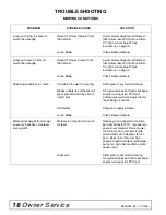
Page 20: ...oo wet for mowing Allow grass to dry before mowing Blades unable to cut that part of grass pressed down by path of tractor tires Slow ground speed of tractor but keep engine running at full PTO rpm Cu...

Page 21: ...lers Check belt for free travel in pulleys Check under mower and around blade spindle shaft for wire rags or other foreign material Clean all material from under mower Frayed edges on belt cover Belt...

Page 22: ...his mower is a jackstand with a load rating of 1000 pounds or more One jackstands under each corner of the mower four total must be installed before working underneath this unit Install jackstands und...

Page 23: ...ll leak and could cause bearing failure 3 Identify the open side of the seal containing the spring 4 Apply a thin coat of Permatex to the area of housing where seals seat 5 Install bottom seal with sp...

Page 24: ...ill gearbox with SAE 80W or 90W gear lube until it runs out the side level plug Repair to this gearbox is limited to replacing bearings seals and gaskets Replacing gears shafts and a housing is not co...

Page 25: ...d remove the driveline from the gearbox 2 Remove vent plug 24 and siphon gear lube from housing through this opening 3 If the leak occurred at either end of horizontal shaft remove oil cap 20 and or o...

Page 26: ...own 13 Remove gear 5 and shim 16 from inside housing 14 Remove bearing 26 by using a punch and hammer from the top outside the housing 15 Support housing upside down top cover surface and remove beari...

Page 27: ...nput shaft end float by moving the input shaft 3 by hand If end float is higher than 0 012 insert shim between input shaft 3 and rear bearing 7 Repeat until end float is less than 0 012 Check rotation...

Page 28: ...der idler pulley to align with drive pulley 2 Tighten gear stand hardware 3 Fill gearbox half full with SAE 90W gear lube 4 Check level after waiting five minutes to permit lube to work through bearin...

Page 29: ...t to disturb needle bearings Insert another bearing cup directly across from first cup and press in as far as possible with hand pressure 2 Trap cups in vise and apply pressure Be sure journal cross i...

Page 30: ...ely block up all corners with jackstands and check stability Secure blocking prevents equipment from dropping due to hydrau lic leak down hydraulic system failures or mechanical component failures Alw...

Page 31: ...g against deck bracket but not fully torqued NOTE Refer to Front Caster Wheel Interference Check page 11 for possible front caster arm posi tions 4 Attach front caster arm in desired position and tigh...

Page 32: ...ough bearings then check to make sure oil level is at bottom of side hole Replace side plug Install vent plug IMPORTANT Gearbox is not filled at the factory Prior to delivery make sure each gearbox is...

Page 33: ...the drive on front of deck 7 Install sleeve 3 on mounting pins and retain with klik pin Install Front Roller Optional 1 Insert four carriage bolts 5 through the front mower frame from inside out 2 Pla...

Page 34: ...wed ___ Present Operator s Manual and request that customer and all operators read it before oper ating equipment Point out the manual safety rules explain their meanings and emphasize the increased s...

Page 35: ...AME ASSEMBLY 34 35 GEARBOX ASSEMBLY 36 DRIVESHAFT ASSEMBLY WALTERSCHEID TWO LOBE 37 BLADE SPINDLE ASSEMBLY 38 REAR CHAIN SHIELDING ASSEMBLY 39 FRONT ROLLER ASSEMBLY OPTIONAL 39 QUICK HITCH OPTIONAL 40...

Page 36: ...aster Arm Asy Right RD6000 2 RD7200 2 or 3 53563 2 Caster Arm Asy Left or 3 52883 4 Caster Arm Asy RD8400 2 4 67318 4 Caster Yoke Shaft Asy RD6000 2 RD7200 2 or 4 52860 4 Caster Yoke Shaft Asy RD8400...

Page 37: ...28 15 32 Long 42 4378 Washer Flat Standard 5 16 43 39254 Screw HHCS 8mm x 1 25P x 16mm 44 62153 Bolt Flanged Whiz 3 8 NC x 1 REF PART QTY DESCRIPTION 45 855 Washer Lock 1 2 46 24537 Washer Flat 50 x...

Page 38: ...Bearing 8 20888 1 Washer Protective Flat 9 1 Pin Cotter B4 x 50 10 57466 2 Snap Ring 11 57467 1 Snap Ring 12 57373 1 Spacer 35 5 x 48 x 2 5 13 57328 2 Kit Shim 60 3 x 71 6 14 57468 1 Nut Castle 15 519...

Page 39: ...5 40583 1 Drive Tube Inner Profile 6 40584 1 Drive Tube Outer Profile 7 40573 1 Yoke Outer Profile 12 40776 2 Bearing Ring Guard 13 40777 2 Chain Guard Anti Rotation REF PART QTY DESCRIPTION 14 40778...

Page 40: ...50 x 2 12 x 31 9 52872 Sleeve 1 14 x 1 50 x 55 10 29899 Bearing Cone 11 52882 Spindle Housing with Cups 12 29898 Bearing Cup 14 52852 Shaft Blade Spindle 16 1001513KT Blade Kit High Suction 21 In set...

Page 41: ...66 for RD7200 2 78 for RD8400 2 REF PART QTY DESCRIPTION 3 55345 1 Shield Chain Plate for RD6000 2 only or 3 53554 1 Shield Chain Plate for RD7200 2 only or 3 52885 1 Shield Chain Plate for RD8400 2 o...

Page 42: ...nk Offset 38 x 2 0 x 15 2 1005401 2 Chain 3 8 Proof Coil 38 Link 3 38214 2 Sleeve 91 x 1 44 x 1 25 4 13563 1 Screw HHCS 1 2 NC x 6 GR5 5 6 Washer Flat 1 2 ZP 6 29368 1 Sleeve 50 x 75 x 3 38 7 11900 1...

Page 43: ...7 634 722 979 1020 1383 A SAE SERIES TORQUE CHART SAE Bolt Head Identification SAE Grade 2 No Dashes SAE Grade 5 3 Radial Dashes SAE Grade 8 6 Radial Dashes Diameter Thread Pitch Millimeters Wrench Si...

Page 44: ...city CCW Counter Clockwise CW Clockwise F Female GA Gauge GR 5 etc Grade 5 etc HHCS Hex Head Cap Screw HT Heat Treated JIC Joint Industry Council 37 Degree Flare LH Left Hand LT Left m Meter mm Millim...

Page 45: ...roduct 44 Replacement Parts 45 OPERATION Adjustment Cutting Height 9 Cutting Height Chart 10 Tractor Top Link 10 Attaching Mower to Tractor 9 Front Caster Arm Configuration 10 Front Caster Wheel Inter...

Page 46: ...ct or noncompliance is discovered or should have been discovered routed through the dealer and distributor from whom the purchase was made transportation charges prepaid WOODS shall complete such repa...

Page 47: ...as made transportation charges prepaid WOODS shall complete such repair or replacement within a reasonable time after WOODS receives the product THERE ARE NO OTHER REMEDIES UNDER THIS WARRANTY THE REM...

Page 48: ...trademarks of Woods Equipment Company All other trademarks trade names or service marks not owned by Woods Equipment Company that appear in this manual are the property of their respective companies o...

Reviews: