Dealer Service
29
MAN1331
(09/29/22)
Spindle Disassembly
1.
Place spindle assembly in press and press shaft
down through housing.
2.
Remove components from shaft.
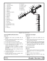
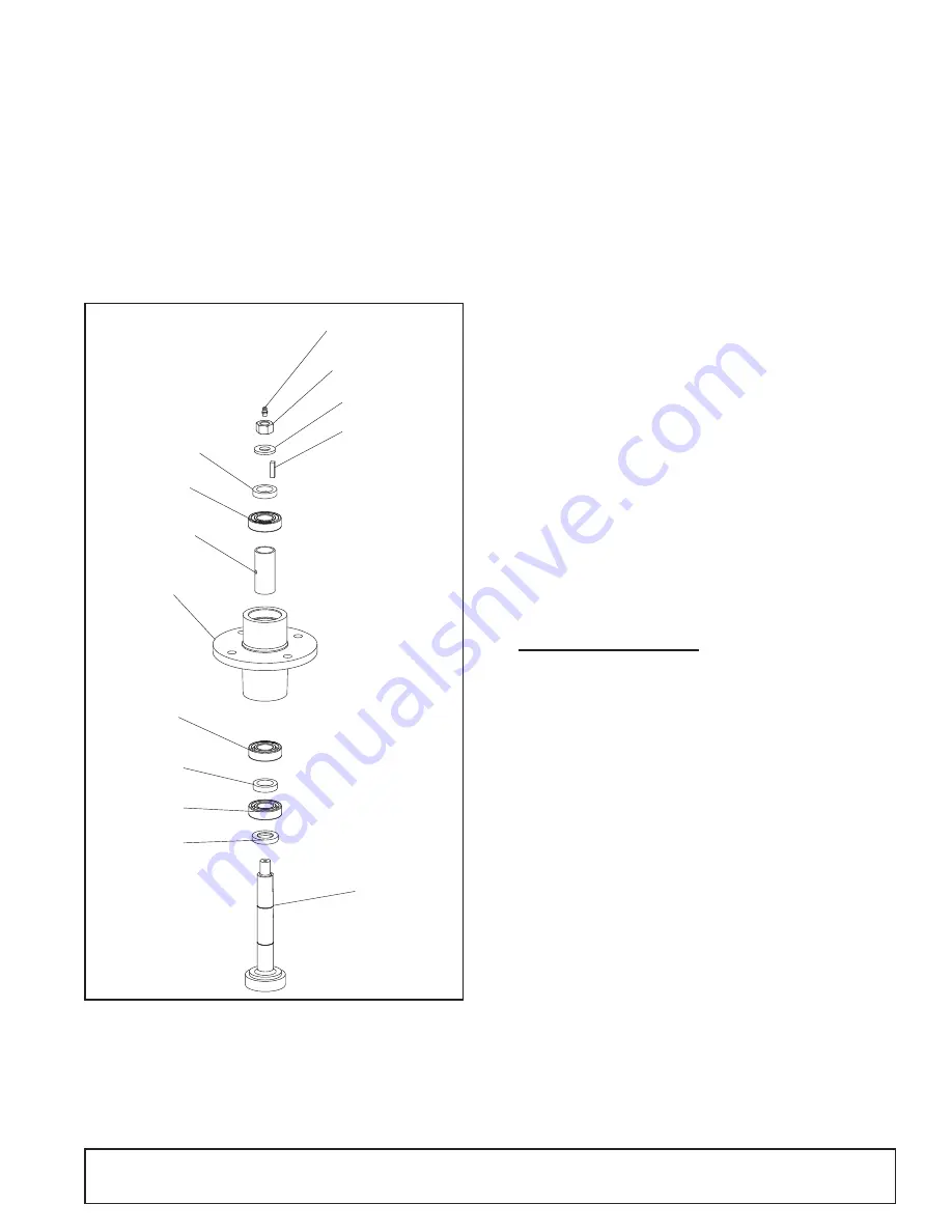
Spindle Assembly
(Figure 18)
■ Improper positioning of seals can cause seal
damage. An improperly installed seal will leak
and could cause bearing failure.
Figure 18.
Spindle and Shaft Assembly
Bearing cones and cups are designed to work together.
It is important to position them so bearing cone taper
mates with cup taper.
1.
Install spacer (18) on shaft with bevel side down.
2.
Place bearing (16) on shaft with seal facing down.
3.
Install sleeve (12) and bearing (14) on shaft.
4.
Install sleeve (15) on shaft.
5.
Install shaft into spindle from bottom up.
6.
Install bearing (16) with seal up onto shaft.
7.
Install sleeve (12) key (11), washer (6) on shaft.
8.
Rotate housing on spindle shaft, checking for free
movement.
9.
Install grease fitting in spindle shaft and grease
spindle.
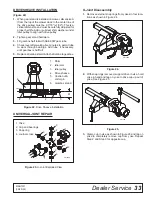
Spindle Installation
■ Pulley installation sequence is very important
for bearing life. Follow the sequence exactly.
1.
Install spindle through bottom of mower and secure
with four mounting bolts.
2.
Install pulley on spindle shaft.
3.
Install hardened washer and nut on pulley and tight-
en to 100 ft-lbs.
GEARBOX SERVICE
Gearbox Removal from Mower
(Figure 19)
1.
Disconnect and remove the rear driveline from the
gearbox.
2.
Remove vent plug and siphon gear lube from hous-
ing through this opening.
3.
Remove gearbox from mower deck by removing
four flanged lock nuts (16) and four carriage bolts
(21).
4.
Remove four cap screws (17) and remove shield
(13) from gearbox.
5.
Remove cotter pin (36) and castle nut (37) from out-
put shaft of gearbox.
6.
Remove sheave (8) from gearbox.
NOTICE
NOTICE
9
10
6
11
13
CD9273 AB
12
16
15
17
14
12
16
18

