background image

Introduction 

3

MAN1331 

(09/29/22)

TABLE OF CONTENTS

INTRODUCTION.   .   .   .   .   .   .   .   .   .   .   .   .   .   .   .   .   .   .   .   .   .   .   .   .   .   .   .   .   .   .   .   .   .   .   .   .   .   .   .   .   .   .   .   .   .   . 2

SPECIFICATIONS  . . . . . . . . . . . . . . . . . . . . . . . . . . . . . . . . . . . . . . . . 4
GENERAL INFORMATION . . . . . . . . . . . . . . . . . . . . . . . . . . . . . . . . . . . . 4

SAFETY . . . . . . . . . . . . . . . . . . . . . . . . . . . . . . . . . . . . . . . . . . . . . . . . . . . 5

SAFETY RULES . . . . . . . . . . . . . . . . . . . . . . . . . . . . . . . . . . . . . . . . . 5

TRAINING  . . . . . . . . . . . . . . . . . . . . . . . . . . . . . . . . . . . . 5
PREPARATION .   .   .   .   .   .   .   .   .   .   .   .   .   .   .   .   .   .   .   .   .   .   .   .   .   .   .   .   .   .   .   .   .   .   5
TRANSPORTATION . . . . . . . . . . . . . . . . . . . . . . . . . . . . . . . 6
OPERATION . . . . . . . . . . . . . . . . . . . . . . . . . . . . . . . . . . . 7
MAINTENANCE  . . . . . . . . . . . . . . . . . . . . . . . . . . . . . . . . . 8
STORAGE  . . . . . . . . . . . . . . . . . . . . . . . . . . . . . . . . . . . . 8

SAFETY & INSTRUCTIONAL DECALS  . . . . . . . . . . . . . . . . . . . . . . . . . . . . . 9

OPERATION.   .   .   .   .   .   .   .   .   .   .   .   .   .   .   .   .   .   .   .   .   .   .   .   .   .   .   .   .   .   .   .   .   .   .   .   .   .   .   .   .   .   .   .   .   .   .   .   13

OPERATION . . . . . . . . . . . . . . . . . . . . . . . . . . . . . . . . . . . . . . . . . .  13

ATTACHING MOWER TO TRACTOR . . . . . . . . . . . . . . . . . . . . . .13
INSTALLATION AND REMOVAL OF DRIVELINE (TRACTOR PTO).   .   .   .   .   .   .14
CUTTING HEIGHT ADJUSTMENT .   .   .   .   .   .   .   .   .   .   .   .   .   .   .   .   .   .   .   .   .   .   .   .15
TRANSPORTATION . . . . . . . . . . . . . . . . . . . . . . . . . . . . . . .16
WING OFFSET ADJUSTMENT.   .   .   .   .   .   .   .   .   .   .   .   .   .   .   .   .   .   .   .   .   .   .   .   .   .17
PRE-OPERATION CHECKLIST . . . . . . . . . . . . . . . . . . . . . . . . .18
STARTING AND STOPPING MOWER . . . . . . . . . . . . . . . . . . . . . .18
OPERATING . . . . . . . . . . . . . . . . . . . . . . . . . . . . . . . . . . .18
REMOVING MOWER FROM TRACTOR.   .   .   .   .   .   .   .   .   .   .   .   .   .   .   .   .   .   .   .   .19

OWNER SERVICE.   .   .   .   .   .   .   .   .   .   .   .   .   .   .   .   .   .   .   .   .   .   .   .   .   .   .   .   .   .   .   .   .   .   .   .   .   .   .   .   .   .   .   .   .   20

OWNER SERVICE . . . . . . . . . . . . . . . . . . . . . . . . . . . . . . . . . . . . . . .  20

BLOCKING METHOD  . . . . . . . . . . . . . . . . . . . . . . . . . . . . . .20
LUBRICATION INFORMATION.   .   .   .   .   .   .   .   .   .   .   .   .   .   .   .   .   .   .   .   .   .   .   .   .   .21
BELT SERVICING  . . . . . . . . . . . . . . . . . . . . . . . . . . . . . . . .23
BLADE SERVICING  . . . . . . . . . . . . . . . . . . . . . . . . . . . . . . .24
CLEANING . . . . . . . . . . . . . . . . . . . . . . . . . . . . . . . . . . . .25

TROUBLESHOOTING . . . . . . . . . . . . . . . . . . . . . . . . . . . . . . . . . . . . .  26

DEALER SERVICE . . . . . . . . . . . . . . . . . . . . . . . . . . . . . . . . . . . . . . . . . . . .  28

DEALER SERVICE . . . . . . . . . . . . . . . . . . . . . . . . . . . . . . . . . . . . . . .  28

BLOCKING METHOD  . . . . . . . . . . . . . . . . . . . . . . . . . . . . . .28
BLADE SPINDLE REPAIR . . . . . . . . . . . . . . . . . . . . . . . . . . . .28
GEARBOX SERVICE .   .   .   .   .   .   .   .   .   .   .   .   .   .   .   .   .   .   .   .   .   .   .   .   .   .   .   .   .   .   .29
DRIVE SHEAVE INSTALLATION .   .   .   .   .   .   .   .   .   .   .   .   .   .   .   .   .   .   .   .   .   .   .   .   .33
UNIVERSAL JOINT REPAIR . . . . . . . . . . . . . . . . . . . . . . . . . . .33

ASSEMBLY . . . . . . . . . . . . . . . . . . . . . . . . . . . . . . . . . . . . . . . . . . . . . . . .  35

ASSEMBLY . . . . . . . . . . . . . . . . . . . . . . . . . . . . . . . . . . . . . . . . . . .  35

DEALER SET-UP INSTRUCTIONS  . . . . . . . . . . . . . . . . . . . . . . .35
OPTIONAL EQUIPMENT .   .   .   .   .   .   .   .   .   .   .   .   .   .   .   .   .   .   .   .   .   .   .   .   .   .   .   .   .37

DEALER CHECKLISTS .   .   .   .   .   .   .   .   .   .   .   .   .   .   .   .   .   .   .   .   .   .   .   .   .   .   .   .   .   .   .   .   .   .   .   .   .   .   .   .   .   .   40

PARTS INDEX .   .   .   .   .   .   .   .   .   .   .   .   .   .   .   .   .   .   .   .   .   .   .   .   .   .   .   .   .   .   .   .   .   .   .   .   .   .   .   .   .   .   .   .   .   .   .   41

APPENDIX.   .   .   .   .   .   .   .   .   .   .   .   .   .   .   .   .   .   .   .   .   .   .   .   .   .   .   .   .   .   .   .   .   .   .   .   .   .   .   .   .   .   .   .   .   .   .   .   .   66

BOLT TORQUE CHART  . . . . . . . . . . . . . . . . . . . . . . . . . . . . . . . . . . . .  66
BOLT SIZE CHART & ABBREVIATIONS . . . . . . . . . . . . . . . . . . . . . . . . . . . .  68

INDEX . . . . . . . . . . . . . . . . . . . . . . . . . . . . . . . . . . . . . . . . . . . . . . . . . . .  69

PRODUCT WARRANTY.   .   .   .   .   .   .   .   .   .   .   .   .   .   .   .   .   .   .   .   .   .   .   .   .   .   .   .   .   .   .   .   .   .   .   .   .   .   .   .   .   .   70

REPLACEMENT PARTS WARRANTY . . . . . . . . . . . . . . . . . . . . . . . . . . . . . . . . . .  71

This Operator’s Manual should be regarded as part of the machine. 

Suppliers of both new and second-hand machines must make sure

that this manual is provided with the machine.

Summary of Contents for TURF BATWING TBW12.40

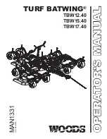
Page 1: ...OPERATOR S MANUAL OPERATOR S MANUAL Rev 9 29 2022 MAN1331 TURF BATWING TBW12 40 TBW15 40 TBW17 40...

Page 2: ...leaning and upkeep Lubricate the unit as specified Observe all safety information in this manual and safety decals on the equipment For service your authorized Woods dealer has trained mechanics genui...

Page 3: ...R 19 OWNER SERVICE 20 OWNER SERVICE 20 BLOCKING METHOD 20 LUBRICATION INFORMATION 21 BELT SERVICING 23 BLADE SERVICING 24 CLEANING 25 TROUBLESHOOTING 26 DEALER SERVICE 28 DEALER SERVICE 28 BLOCKING ME...

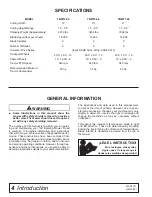
Page 4: ...ad it carefully It furnishes information and instructions that will help you achieve years of dependable perfor mance These instructions have been compiled from extensive field experience and engineer...

Page 5: ...all hydraulic functions several times Do this before putting into service or al lowing anyone to approach the equipment Route hydraulic hoses carefully to prevent dam age Hoses must not be twisted ben...

Page 6: ...o the oper ator the operator s clothing or the tractor seat Make test turns both left and right Check that both the hydraulic hose and the mower trans port lock release rope do not become taut or caug...

Page 7: ...sponsible adult other than the operator Do not carry children even with the blade s shut off Children could fall off and be seriously injured or interfere with safe machine operation Children who have...

Page 8: ...d repair parts Substitute parts may not meet original equipment specifi cations and may be dangerous To prevent contamination clean and then cover hose ends fittings and hydraulic ports with tape Do n...

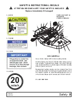
Page 9: ...als when using a pres sure washer high pressure water can enter through very small scratches or under edges of decals causing them to peel or come off Replacement safety decals can be ordered free fro...

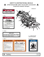
Page 10: ...securely attached at both ends n Driveline guards that turn freely on driveline n Read the operator s manual n Do not use PTO adapters 18864 2 1 5 CD9266 AC 11 21 15 4 3 6 1 5 1 16 13 22 7 WING DECK...

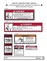
Page 11: ...865 11 632854 DANGER GUARDMISSING DO NOT OPERATE 33347 DANGER DANGER GUARDMISSING DO NOT OPERATE 4 33347 2 5 x 7 Black and PMS 186 632865 AA RAISED MOWER CAN DROP AND CRUSH n Before working underneath...

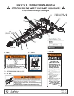
Page 12: ...e parking brake is engaged before going between tractor and implement Stand clear of machine while in operation or when it is being raised or lowered FAILURE TO FOLLOW THESE INSTRUCTIONS COULD RESULT...

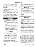
Page 13: ...o not exceed Make sure spring activated locking pin or collar slides freely and is seated firmly in tractor PTO spline groove Stop power unit and implement immediately upon striking an obstruction Dis...

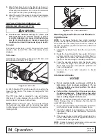
Page 14: ...lines and or electrical cables used to operate the towed machine shall have more slack than the safety chain so that if a failure of the primary attaching system should occur trailer will remain oper...

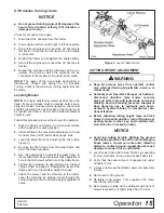
Page 15: ...arking jack to adjust the trailer frame to the level position Align the nearest hitch adjustment hole in the hitch clevis with a hole in the trailer frame 6 Tighten the hardware to specifications in t...

Page 16: ...r short distances raise the wings and the rear deck until all three transport locks engage automatically Install locking pins to secure the mower wings for trans port as shown in Figure 5 and Figure 6...

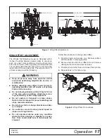
Page 17: ...uipment Do not operate or transport on steep slopes Refer to tractor manual for proper ballasting and slope recommendations Do not stop start or change directions sudden ly on slopes Use extreme care...

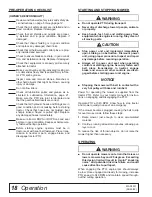
Page 18: ...mission in neutral or park engage brake and disengage tractor PTO STARTING AND STOPPING MOWER Do not operate PTO during transport Never direct discharge toward people animals or property Keep hands fe...

Page 19: ...stones branches or other hard objects that might be thrown caus ing injury or damage Extremely tall material should be cut twice Set mower at a higher cutting height for the first pass Then cut at des...

Page 20: ...components are lowered to the ground and system pressure is released by operating all valve control levers Before dismounting power unit or perform ing any service or maintenance follow these steps d...

Page 21: ...AE 90W gear lube in gearboxes Check level of oil in gearboxes using provided dipstick in vent plug or until oil runs out of side plug Daily lubrication of PTO slip joints is necessary Failure to maint...

Page 22: ...8 9 REF DESCRIPTION FREQUENCY 1 Caster Wheel Pivots 8 Hours 2 Caster Wheel Hubs 8 Hours 3 Blade Spindles 24 Hours 4 Gearbox Fill 1 2 full with SAE 90W gear lube Check For Leaks Daily 5 Driveline U Jo...

Page 23: ...und indicates broken cords Alternate Removal Method 1 Insert 1 2 ratchet or breaker bar into square hole on idler arm Rotate idler arm clockwise to remove tension on belt Obtain enough belt length to...

Page 24: ...eep all persons away from operator control area while performing adjustments service or maintenance Frequently check blades They should be sharp free of nicks and cracks and securely fastened 1 Raise...

Page 25: ...due etc from machine Remove belt shields and clean out all accumu lated grass dirt and other debris Inspect machine and replace worn or damaged parts Replace any safety decals that are missing or not...

Page 26: ...s in swath Conditions too wet for mowing Allow grass to dry before mowing Blades unable to cut that part of grass pressed down by path of tractor tires Slow ground speed of tractor but keep engine run...

Page 27: ...wer Frayed edges on belt cover Belt is misaligned Re align belt Be sure belt does not rub any other part while running Pulley is misaligned Inspect to ensure belt is running in center of backside idle...

Page 28: ...t for eyes hair hands hearing and head and respirator or filter mask where appropriate BLOCKING METHOD NOTE See Blocking Method pg 20 BLADE SPINDLE REPAIR Spindle Repair Spindle repair requires specia...

Page 29: ...key 11 washer 6 on shaft 8 Rotate housing on spindle shaft checking for free movement 9 Install grease fitting in spindle shaft and grease spindle Spindle Installation Pulley installation sequence is...

Page 30: ...al shaft gasket or seal can be repaired without removing the gearbox from the mower Seal Installation NOTE Proper seal installation is important An improp erly installed seal will leak 1 Clean area in...

Page 31: ...the gearbox 2 Remove vent plug 24 and siphon gear lube from housing through this opening 3 If the leak occurred at either end of horizontal shaft remove oil cap 20 and or oil seal 19 Replace with new...

Page 32: ...output shaft 4 and secure with washer 17 castle nut 14 and cotter pin 9 7 Apply grease to lower seal lips 18 and press seal over output shaft 4 using a tube of the correct di ameter Be sure not to da...

Page 33: ...gearbox is half full 5 Replace driveline shield Attach driveline to gearbox Figure 22 Drive Sheave Installation UNIVERSAL JOINT REPAIR Figure 23 U Joint Exploded View U Joint Disassembly 1 Remove exte...

Page 34: ...from first cup and press in as far as possible with hand pressure 2 Trap cups in vise and apply pressure Be sure journal cross is started into bearings and continue pressure with vise squeezing in as...

Page 35: ...rotec tive equipment for eyes hair hands hearing and head and respirator or filter mask where appropriate Do not work underneath mower unless it is properly attached to tractor and blocked se curely W...

Page 36: ...al times Do this before putting into service or al lowing anyone to approach the equipment Attach the mower hydraulic hose to the tractor port Hydraulic quick coupler is not supplied NOTE The mower hy...

Page 37: ...4 6 7 9 9 9 2 4 5 4 8 7 1 1 Kit Rear Roller 2 HHCS 1 2 NC X 6 GR5 3 Bolt CRG 3 8 NC X 1 GR5 ZP 4 Washer Flat 1 2 SAE ZP 5 Roller 2 X 4 38 6 Lug Bent Antiscalp Roller RH 7 Nut 1 2 Flange Lock Nut 8 Lu...

Page 38: ...BRG 6203 6 Washer Flat 1 2 SAE ZP 7 HHCS 1 2 NC X 9 GR5 8 Nut Lock 1 2 NC Flange 9 BOLT CRG 3 8 NC X 1 GR5 ZP 10 Nut HEX FLNG Lock 3 8 NC 5 2 3 CD9281 AA 4 6 1 1 Kit Chain Shield 48 1 Kit Chain Shield...

Page 39: ...be pointing upward 5 Attach rod end of cylinder 3 to item 2 using items 7 8 and 9 6 Install reducers 4 elbows 5 and hoses to base of cylinder TBW Hitch Option Figure 35 TBW Hitch Option 7 7 6 5 6 5 1...

Page 40: ...llar slides freely and is seated in groove on tractor PTO shaft Show customer how to determine the turning limits of the CV PTO driveline Show customer the safe proper procedures to be used when mount...

Page 41: ...52 HUB AXLE ASSEMBLY 52 18 CASTER ARM WHEEL ASSEMBLY 53 15 CASTER ARM WHEEL ASSEMBLIES 54 TBW15 40 17 40 WING GEARBOX REAR DECK GEARBOX 55 TBW12 40 WING GEARBOX 55 BLADE SPINDLE ASSEMBLY 56 FRONT ROLL...

Page 42: ...2 29 33 40 63 64 10 60 59 45 45 46 42 44 43 28 38 37 32 31 30 32 20 11 11 12 12 12 15 14 24 27 25 26 22 23 15 19 20 27 CD9296 AC 26 18 13 5 12 12 51 52 11 11 7 54 53 55 57 53 53 50 58 57 53 17 21 16 2...

Page 43: ...BOLT CRG 1 2 NC X 1 1 4 GR5 35 632568RP 1 WA FRONT STOP MNT TBW12 40 RH 36 632565RP 1 WA FRONT STOP MNT TBW12 40 LH REF PART QTY DESCRIPTION 37 629823RP 2 PLATE BASE STAND TBW15 40 17 40 38 3508 8 HH...

Page 44: ...70 47 53 5 4 8 CD9282 AB 65 38 49 50 68 33 71 54 41 41 52 2 3 6 7 6 19 21 22 26 23 32 33 34 30 6 31 36 35 39 40 44 42 43 45 46 45 48 45 48 44 25 47 55 56 57 58 59 60 61 62 64 63 41 66 21 22 23 67 37...

Page 45: ...1 W7701 12 BOLT PLOW 3 8 NC X 1 42 6697 2 BOLT CRG 3 8 NC X 1 GR5 ZP 43 630693RP 1 FLAT 18X1 5X17 WING STP TBW15 40 17 40 REF PART QTY DESCRIPTION 44 90001708 2 BOLT CRG 3 8 NC X 4 1 2 GR5 ZP 45 W7006...

Page 46: ...10 1029549 2 WA PIN 1 00 X 9 09 11 1285 4 1 4 X 1 1 2 COTTER PIN 12 W8348 2 PIN HDLS 1 00 X 5 58 13 58984 2 WA REAR WING PIN 14 613748 1 DRIVELINE CMPL 35 3 X 52 0 REF PART QTY DESCRIPTION 15 631404...

Page 47: ...14 1006404 1 HOSE 25 108 9 16 JICF 1 4 NPTM 15 1006400 1 FTNG BLKHD 9 16JICM X 1 4 NPTM 16 1006403 1 HOSE 25 48 9 16 JICF 9 16 JICM 17 1006402 2 HOSE 25 33 9 16 JICF 9 16 JICM REF PART QTY DESCRIPTIO...

Page 48: ...MAN1331 09 29 22 1 3 4 5 6 7 7 13 14 15 9 17 36 37 36 19 18 31 31 CD9283 AA 9 28 4 34 35 20 4 4 10 16 18 10 10 24 33 7 9 25 26 25 2 32 29 7 7 11 12 27 30 21 22 8 41 40 39 38 4 23 32 TBW12 40 QTY 1 RE...

Page 49: ...B 23 616100 1 SPINDLE BALL BEARING ASY 24 66661 1 SLV 626 X 1 00 X 1 26 25 35141 2 RETAINING RING INT 26 35193 2 BRG 6203 27 20419 1 BOLT CRG 5 8 NC X 3 GR5 ZP 28 3379 11 BOLT HEX 1 2 NC X 1 50 GR5 2...

Page 50: ...ELT W76 ARAMID 16 11900 24 NUT LOCK 1 2 NC FLANGE 17 609225 5 NUT HFN 5 8 NC LOCK 18 1041071 4 BOLT HEX FLNG M8 X16 CL8 8 DRI LOC 19 35141 2 RETAINING RING INT 20 1008113 1 SLV 1 25 X 1 75 X 75 21 163...

Page 51: ...88 CAP HOOK 12 35193 2 BRG 6203 13 1002048 1 CLUTCH SHIELD 100 143 MM BC 14 616093 1 V BELT W95 ARAMID 14 616092 1 V BELT W116 ARAMID 15 11900 17 NUT LOCK 1 2 NC FLANGE 16 609225 7 NUT HFN 5 8 NC LOCK...

Page 52: ...50 8 7163 1 WSHR 1 1 4 STD FLAT 9 15134 1 PIN SPIROL 25 X 1 00 REF PART QTY DESCRIPTION 1 1001020RP 1 WHEEL HUB AXLE ASSEMBLY 2 1001021RP 1 AXLE SHAFT 3 314 1 SEAL 1 50 X 2 44 X 31 4 2303 2 BEARING CO...

Page 53: ...4 HT 11 1031773 3 SLV HT 525 X 750 X 10 65 12 1031793 3 HHCS 1 2NC X 13 GR5 YD REF PART QTY DESCRIPTION 13 1093 3 NUT HEX 1 2 NC PLTD 14 11900 3 NUT LOCK 1 2 NC FLANGE 15 58987 4 PIPE 1 1 2 SCDL 80 X...

Page 54: ...8 X 1 1 4 HT 11 1093 2 NUT HEX 1 2 NC PLTD REF PART QTY DESCRIPTION 12 11900 20 NUT LOCK 1 2 NC FLANGE 15 12296 10 1 4 28 STRT G FTG 15 32L 16 31780 12 BUSHING 1 1 4 X 1 1 2 X1 1 2BR 16 52855 12 PIPE...

Page 55: ...X 14MM 24 57076 1 PLUG BREATHER 1 2 25 1 PIN COTTER 5 X 50 REF PART QTY DESCRIPTION 26 57478 1 BEARING 27 20890 1 BALL BEARING NS NOT SERVICED STANDARD HARDWARE OBTAIN LOCALLY REF PART QTY DESCRIPTION...

Page 56: ...1 00 B 5 616067 3 6 SHEAVE 4 00 PD X 1 00 B 5 616064 3 9 SHEAVE 4 75 PD X 1 00 B 6 57817 9 9 9 WSHR 5 8 SAE FLAT HRDN 7 3379 36 36 36 BOLT HEX 1 2 NC X 1 50 GR5 8 11900 36 36 36 NUT LOCK 1 2 NC FLANG...

Page 57: ...NC X 9 GR5 8 11900 1 NUT LOCK 1 2 NC FLANGE 9 6697 3 BOLT CRG 3 8 NC X 1 GR5 ZP 10 14350 3 NUT HEX FLNG LOCK 3 8 NC REAR ROLLER ASSEMBLY OPTIONAL 2 CD9279 AA 3 4 5 4 6 7 9 9 9 2 4 5 4 8 7 1 REF PART Q...

Page 58: ...CHAIN SHIELD 60 1 2 1 616076 KIT CHAIN SHIELD 72 1 3 2 6266443RP PLATE 48 CHAIN SHIELD 2 2 613771RP PLATE 60 CHAIN SHIELD 1 2 2 613772RP PLATE 72 CHAIN SHIELD 1 3 3 6697 3 8 NC X 1 CARRIAGE BOLT X X...

Page 59: ...1 613791 1 FITTING GREASE ZERK NIPPLE M6 1 12 1044051 1 COMPLETE COLLAR YOKE C12 1 3 8 6 13 636628 1 CROSS BEARING KIT 14 636627 1 COMPLETE COLLAR YOKE REAR DECK DRIVE REF PART QTY DESCRIPTION 1 61374...

Page 60: ...collar repair kit 12 1001306 1 Inner tube yoke 13 1001305 1 Flexible pin 14 1026991 1 Outer yoke tube 15 1026992 1 Inner yoke tube TBW15 40 WING DRIVE REF PART QTY DESCRIPTION A 1023227 Drive Cmpl 40...

Page 61: ...INE 2 632889 1 DRIVELINE HALF FRONT W CV 3 632890 1 DRIVELINE HALF REAR 4 632891 1 GUARD OUTER 5 632893 1 GUARD INNER 6 632896 1 U JOINT BEARING FRONT 7 632895 1 LOCK COUPLER REAR 8 632897 1 U JOINT B...

Page 62: ...oke 2 36990 1 U Joint repair kit 3 1011756 1 Yoke outer 4 1001330 1 Flexible pin 5 1028776 1 Outer bearing ring 6 30922 6 Retainer shield 7 1011757 1 Centering ring REF PART QTY DESCRIPTION 8 1011755...

Page 63: ...od seal 2C 1 Rod O ring 2D 2 Cap seal 2E 2 Cap O ring 2F 2 Piston seal 2G 1 Piston O ring 3 N S N S 1 Cylinder housing rod end 4 N S N S 1 Piston 5 N S N S 1 Jam nut 6 N S N S 4 Cylinder tie rod 7 3 1...

Page 64: ...ZP 5 2 BOLT CRG 1 4 NC X 3 4 6 2 NUT LOCK 1 4 NC FLANGE 7 2 HHCS 1 4 NC X 3 4 GR5 8 10 NUT HEX FLNG 1 4 NC SRTD 9 1040275 1 LED AG COMBO LAMP LH 10 8 HHCS 1 4 NC X 1 GR5 11 630695 2 SCREW SELF TAP 10...

Page 65: ...ARD FLAT WASHER 11 839 HHCS 3 8 NC X 1 GR5 12 14350 NUT 3 8 NC FLANGE LOCK 13 636643 1 WA SPACER ALIGNMENT 14 3699 HHCS 1 2 NC X 2 GR5 15 854 WASHER 1 2 HHCS HEX HEAD CAP SCREW STANDARD HARDWARE OBTAI...

Page 66: ...given to specifications used on hardware defined by SAE J1701 MAR 99 J1701M JUL 96 SAE SERIES TORQUE CHART SAE Bolt Head Identification SAE Grade 2 No Dashes SAE Grade 5 3 Radial Dashes SAE Grade 8 6...

Page 67: ...6 11 8 8 6 11 8 6 x 1 0 8 x 1 25 13 mm 20 15 27 20 21 16 29 22 8 x 1 0 10 x 1 5 16 mm 39 29 54 40 41 30 57 42 10 x 1 25 12 x 1 75 18 mm 68 50 94 70 75 55 103 76 12 x 1 25 14 x 2 0 21 mm 109 80 151 111...

Page 68: ...Standard Pipe Tapered Male CV Constant Velocity CCW Counter Clockwise CW Clockwise F Female FT Full Thread GA Gauge GR 5 etc Grade 5 etc HHCS Hex Head Cap Screw HT Heat Treated JIC Joint Industry Cou...

Page 69: ...2 Product Registration 2 Specifications 4 Table of Contents 3 Warranty Product 70 Replacement Parts 71 OPERATION Adjustment Cutting Height Chart 16 Attaching Mower to Tractor 13 Attaching Hydraulic Ho...

Page 70: ...s Warranty is limited to at WOODS option the repair or replacement free of charge of the product if WOODS in its sole discretion deems it to be defective or in noncompliance with this Warranty The pro...

Page 71: ...e returned to WOODS with proof of purchase within thirty 30 days after such defect or noncompliance is discovered or should have been discovered routed through the dealer and distributor from whom the...

Page 72: ...m 2022 Woods Equipment Company All rights reserved Woods and the Woods logo are trademarks of Woods Equipment Company All other trademarks trade names or service marks not owned by Woods Equipment Com...

Reviews: