Assembly
35
MAN1331
(09/29/22)
ASSEMBLY
DEALER SET-UP INSTRUCTIONS
The mower is shipped mostly assembled but requires
dealer set-up. The Woods dealer should deliver the
mower to the owner completely assembled, lubricated,
and adjusted for normal conditions.
Recommended torque values for hardware are located
on page 66.
Complete check lists on page 40 when assembly is
complete.
■ Keep hands and body away from pressurized
lines. Use paper or cardboard, not hands or
other body parts to check for leaks. Wear safe-
ty goggles. Hydraulic fluid under pressure can
easily penetrate skin and will cause serious in-
jury or death.
■ Make sure that all operating and service person-
nel know that if hydraulic fluid penetrates skin,
it must be surgically removed as soon as possi-
ble by a doctor familiar with this form of injury
or gangrene, serious injury, or death will result.
CONTACT A PHYSICIAN IMMEDIATELY IF FLUID
ENTERS SKIN OR EYES. DO NOT DELAY.
■ Make sure spring-activated locking pin or collar
slides freely and is seated firmly in tractor PTO
spline groove.
■ Always wear relatively tight and belted clothing
to avoid getting caught in moving parts. Wear
sturdy, rough-soled work shoes and protec-
tive equipment for eyes, hair, hands, hearing,
and head; and respirator or filter mask where
appropriate.
■ Do not work underneath mower unless it is
properly attached to tractor and blocked se-
curely. When properly attached, the unit will be
anchored to minimize front to rear movement.
■ Do not allow bystanders within 25 feet (7.62 m)
of the area when operating, attaching, remov-
ing, assembling, or servicing equipment.
Remove Shipping Straps
1.
Park mower on level hard surfaced area.
2.
Remove front drive line from rear deck.
3.
Attach drive line to stub shaft (see trailer assembly).
NOTE:
Make sure CV drive is located on tractor
side.
4.
Lift back of rear deck with a hoist/chain rated for 500
lbs to take tension off of rear chains.
5.
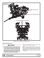
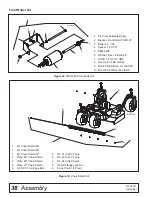
Remove 3/8" bolts, washers, and nuts from both
rear lift chains. See Figure 30. This hardware is for
factory shipping purposes only an can be discarded.
Figure 29.
Remove Shipping Hardware
6.
Gently lower deck until the deck is supported by the
lift chains.
7.
Remove 1/2" lock nuts and remove shipping strap
from between right and left decks. Figure 30.
Reinstall 1/2" lock nuts on front bolts and tighten to
85 ft-lbs.
8.
Install jack in front tongue connection and adjust it
to support front weight of unit and level tongue.
9.
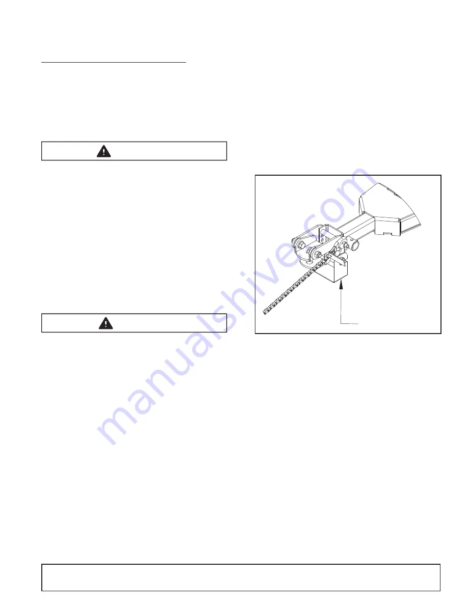
Remove front shipping bracket channel shown in
Figure 29 and retighten hardware to 170 ft-lbs.
WARNING
CAUTION
REMOVE BRACKET
CD9276 AA


