16
Operation
MAN0826 (8/31/2010)
TRANSPORT
When transporting the mower short distances, raise
the wings and the rear deck until all three transport
locks engage automatically.
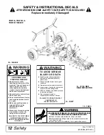
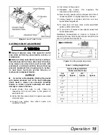
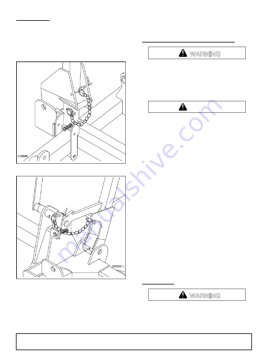
Install locking pins to secure the mower wings for
transport as shown in Figure 4 and Figure 5.
Figure 4
. Lock Pin Installed (Right Wing)
Figure 5
. Lock Pin Storage Installed
(Rear Deck)
To lower the wings and the rear deck:
1.
Remove the locking pins and store in holes
provided.
2.
Slightly raise the wings and rear deck to take
pressure off the locking mechanisms.
3.
Pull the transport lock release rope to disengage
the locks. Lower the wings and rear deck and
release the rope.
STARTING AND STOPPING MOWER
Do not operate PTO during transport.
Never direct discharge toward people, animals,
or property.
Keep hands, feet, hair, and clothing away from
equipment while engine is running. Stay clear of all
moving parts.
Stop power unit and implement immediately
upon striking an obstruction. Dismount power unit,
using proper procedure. Inspect and repair any
damage before resuming operation.
Always sit in power unit seat when operating
controls or starting engine. Securely fasten seat
belt, place transmission in neutral, engage brake,
and ensure all other controls are disengaged
before starting power unit engine.
NOTICE
■
Stopping the mower with belt in contact with a
very hot pulley will bake and ruin belt.
Power for operating the mower is supplied from the
tractor PTO. Refer to your tractor manual for instruc-
tions on engaging and disengaging the PTO.
Operate PTO at 540 rpm. Know how to stop tractor and
mower quickly in case of an emergency.
If the mower becomes plugged causing the belt to slip
for over two seconds, follow these steps:
1.
Raise mower just enough to clear accumulated
material.
2.
Continue running at least two minutes, allowing
pulleys to cool.
To reduce the risk of thrown objects, do not raise the
mower higher than necessary
OPERATING
Do not operate mowers on terrain that raises
mowers beyond 25 degrees. Exceeding this design
limit will result in U-joint “knocking noise” and
potential driveline failure and could cause driveline
to pull apart.
WARNING
CAUTION
WARNING
Summary of Contents for Turf Batwing TBW144
Page 1: ...OPERATOR S MANUAL TURF BATWING MAN0826 Rev 11 15 2013 TBW144 TBW180 TBW204...
Page 39: ...Assembly 39 MAN0826 8 31 2010 NOTES...
Page 42: ...42 Parts MAN0826 8 31 2010 TBW144 TBW180 TBW204 MAIN FRAME ASSEMBLY Rev 11 15 2013...
Page 44: ...44 Parts MAN0826 8 31 2010 TBW144 TBW180 TBW204 TRAILER ASSEMBLY Rev 11 15 2013...
Page 50: ...50 Parts MAN0826 8 31 2010 CASTER ARM WHEEL ASSEMBLY...
Page 56: ...56 Parts MAN0826 8 31 2010 TBW144 TBW180 TBW204 REAR WING DECK DRIVES...

