66
Parts
MAN0826 (8/31/2010)
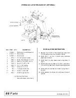
HYDRAULIC LATCH RELEASE KIT (OPTIONAL)
INSTALLATION INSTRUCTION
1.
Remove four 1/3 NC x 2 hex head cap screws and
1/2” flat washers from top of shield on trailer.
2.
Attach item 1 on top of shield using hardware
previously removed.
3.
Attach item 2 to wing release lever using items 10
and 11.
4.
Attach base end of cylinder (3) to item 1 using items
7, 8, and 9. Cylinder ports should be pointing upward
.
5.
Attach rod end of cylinder (3) to item 2 using items 7,
8, and 9.
6.
Install reducers (4), elbows (5), and hoses to base of
cylinder.
REF
PART
QTY
DESCRIPTION
1032454
TBW Hydraulic Latch Release Kit
1
1032479
1
Release Base
2
1032489
1
Slide Channel
3
18725
1
3-1/2 x 8 Hydraulic Cylinder
4
11893
2
Busing, Pipe Reducing 1/2 x 1/74
5
10290
2
Elbow, 90° 3/32 RSTR 1/4 x 1/4
6
17628
2
Hose, HP 1/4 NPT x 108
7
8345
2
Pin, 1 x 4.08 Headless
8
1285
*
Cotter Pin, 1/4 x 1-1/2
9
832
*
1" Standard Flat Washer
10
839
*
3/8 NC x 1 HHCS GR5
11
14350
*
3/8 NC Flange Lock Nut
HHCS
Hex Head Cap Screw
*
Standard hardware, obtain locally
Summary of Contents for Turf Batwing TBW144
Page 1: ...OPERATOR S MANUAL TURF BATWING MAN0826 Rev 11 15 2013 TBW144 TBW180 TBW204...
Page 39: ...Assembly 39 MAN0826 8 31 2010 NOTES...
Page 42: ...42 Parts MAN0826 8 31 2010 TBW144 TBW180 TBW204 MAIN FRAME ASSEMBLY Rev 11 15 2013...
Page 44: ...44 Parts MAN0826 8 31 2010 TBW144 TBW180 TBW204 TRAILER ASSEMBLY Rev 11 15 2013...
Page 50: ...50 Parts MAN0826 8 31 2010 CASTER ARM WHEEL ASSEMBLY...
Page 56: ...56 Parts MAN0826 8 31 2010 TBW144 TBW180 TBW204 REAR WING DECK DRIVES...


