Operation
13
MAN1313 (3/3/2021)
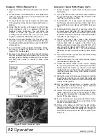
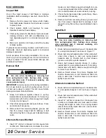
Figure 4
. Hitch Assembly
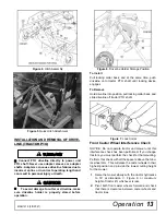
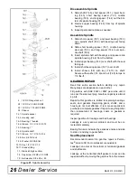
Figure 5
. Quick Hitch Attachment
INSTALLATION AND REMOVAL OF DRIVE-
LINE (TRACTOR PTO)
Connect PTO driveline directly to power unit
PTO shaft. Never use adapter sleeves or adapter
shafts. Adapters can cause driveline failures due to
incorrect spline or incorrect operating length and
can result in personal injury or death.
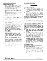
To avoid damage to cutter or driveline, make
sure driveline holder is properly stored before
operation.
Figure 6
. Driveline Holder Storage Position
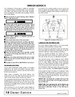
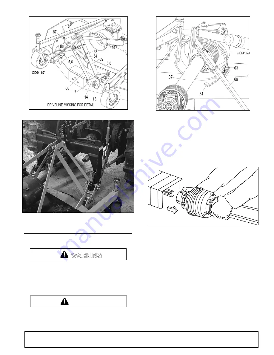
To Install
Pull locking collar back, and at the same time, push
driveline onto tractor PTO shaft until locking device
engages.
To Remove
Hold driveline into position, pull locking collar back, and
slide driveline off tractor PTO shaft.
Figure 7
. Lock Collar
Front Caster Wheel Interference Check
NOTICE:
Do not operate tractor and mower until this
interference check has been performed. If you change
tractors, you must perform the check for that mounting.
Perform this check with all the spacers above the tubu-
lar wheel arm. This will place the caster wheels in their
highest position and provide the lowest cutting height
for the mower.
1.
Raise the mower slowly with the tractor hydraulics
to 16” at dimension C, Figure 8, or maximum
height of tractor lift, whichever is less.
2.
Pivot both front caster wheels forward and check
that there is clearance between caster wheels and
tractor tires.
WARNING
CAUTION

