34
Assembly
MAN1313 (3/3/2021)
12.
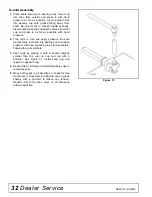
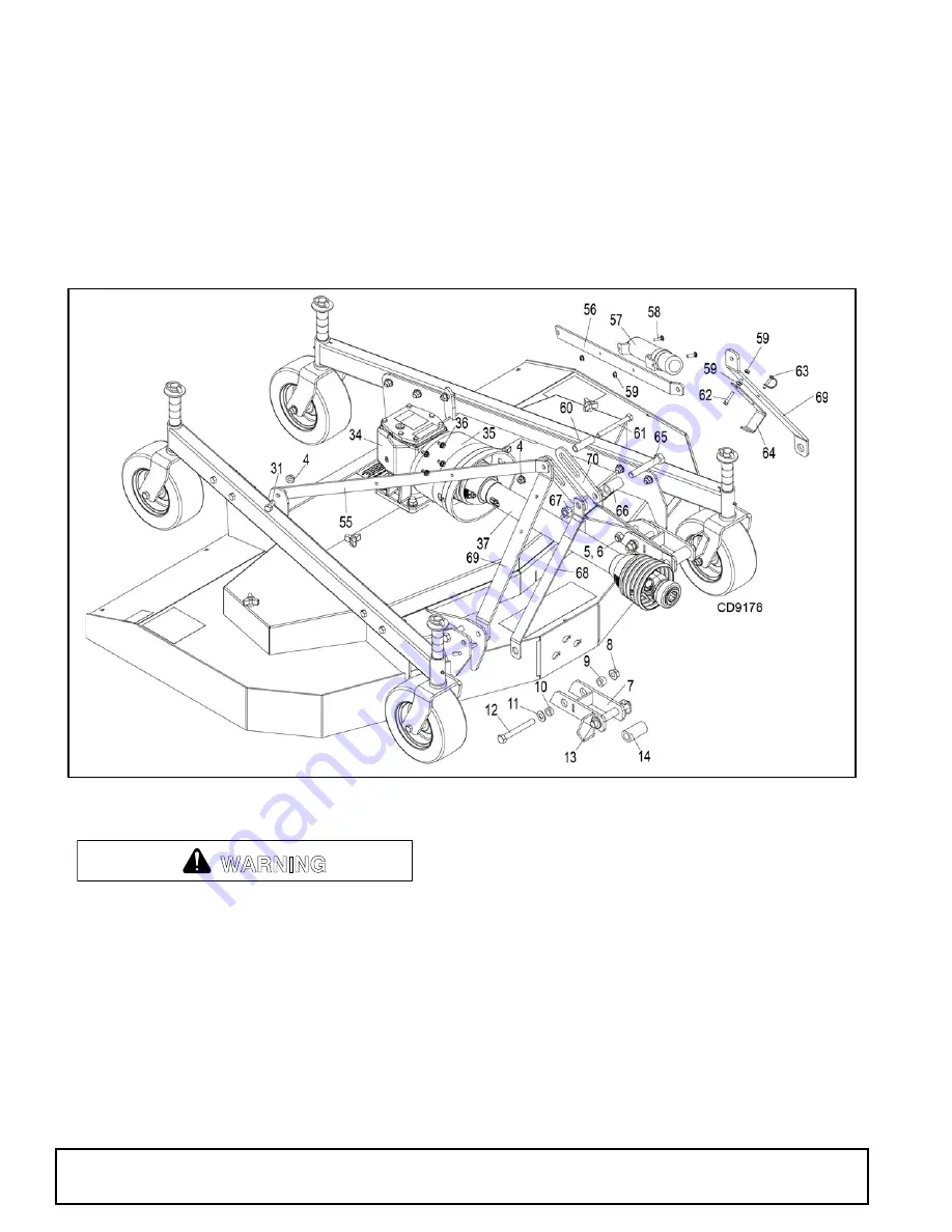
Install 5/8NC x 3-1/2 cap screws (5) through deck
hitch plates behind mower lower hitch links (7) to
keep hitch links level. Retain with 5/8NC lock nuts
(6).
13.
Install quick hitch sleeves (14) over clevis pins (13)
in mower lower hitch links (7). Install mower quick
hitch a-frame bars (68) over the clevis pins on the
inside face of the mower lower hitch links. Retain
with included klik pins.
14.
Position top quick hitch sleeve (66) between
mower top hitch links (70). Align mower quick hitch
a-frame bars (68) on outside of top hitch links.
Ensure alignment of assembly using 3/4NC x 4-1/2
cap screw (65). Retain with ¾ NC lock nut (67).
Tighten then back off 1/4 – 1/2 turn to ensure
assembly moves up and down freely.
CAUTION!:
Pinch Hazard. Hands or fingers could be
pinched between quick hitch a-frame bars and rigid a-
frame bars on mower. Do not push on quick hitch a-
frame bars when mower is disconnected from tractor.
Figure 32
. Hitch Assembly
Connect PTO driveline directly to power unit
PTO shaft. Never use adapter sleeves or adapter
shafts. Adapters can cause driveline failures due to
incorrect spline or incorrect operating length and
can result in personal injury or death.
Driveshaft Installation
1.
Orient the driveline with the implement end toward
the mower gearbox. The implement end uses the
female profile tube (large), which is covered by the
smaller profile shield (plastic tube). Slide the QD
collar back and push the drive yoke onto the
gearbox input shaft. Make sure the QD is seated
securely in the groove of the gearbox shaft.
2.
The tractor end of the driveline uses the male
profile tube (small). The male profile is covered by
the larger profile shield (plastic tube). Slide the QD
collar back to ensure it operates smoothly.
Lubricate if necessary.
3.
Hang the driveline on the driveline holder.
4.
If your driveline came with tether chains, attach the
implement end chain to the gearbox input shield.
WARNING

