background image

-17-

Model W1686 (For Machines Mfd. Since 11/10)

SE

TU

P

Figure.11.

 Working clearances.

Machine.Placement

28

3

/

4

"

25

1

/

4

"

Weight.Load

Refer to the 

Machine.Specifications

 for the 

weight of your machine. Make sure that the 

surface upon which the machine is placed will 

bear the weight of the machine, additional 

equipment that may be installed on the 

machine, and the heaviest workpiece that will 

be used. Additionally, consider the weight of 

the operator and any dynamic loading that may 

occur when operating the machine.

Space.Allocation

Consider the largest size of workpiece that 

will be processed through this machine and 

provide enough space around the machine 

for adequate operator material handling or 

the installation of auxiliary equipment. With 

permanent installations, leave enough space 

around the machine to open or remove doors/

covers as required by the maintenance and 

service described in this manual. 

See.below.for.

required.space.allocation.

Physical.Environment

The physical environment where your machine is 

operated is important for safe operation and the 

longevity of its components. For best results, 

operate this machine in a dry environment 

that is free from excessive moisture, hazardous 

chemicals, airborne abrasives, or extreme 

conditions. Extreme conditions for this type 

of machinery are generally those where the 

ambient temperature range exceeds 41°–104°F; 

the relative humidity range exceeds 20–95% 

(non-condensing); or the environment is subject 

to vibration, shocks, or bumps.

Electrical.Installation

Place this machine near an existing power 

source. Make sure all power cords are protected 

from traffic, material handling, moisture, 

chemicals, or other hazards. Make sure to leave 

access to a means of disconnecting the power 

source or engaging a lockout/tagout device.

Lighting

Lighting around the machine must be adequate 

enough that operations can be performed 

safely. Shadows, glare, or strobe effects that 

may distract or impede the operator must be 

eliminated.

Children. or. untrained. people.

may.be.seriously.injured.by.this.

machine..Only.install.in.an.access.

restricted.location.

Summary of Contents for Shop Fox W1686

Page 1: ...4 3482 Online Technical Support techsupport woodstockint com COPYRIGHT AUGUST 2002 BY WOODSTOCK INTERNATIONAL INC REVISED JULY 2018 MN WARNING NO PORTION OF THIS MANUAL MAY BE REPRODUCED IN ANY SHAPE...

Page 2: ...g grinding tool integrity and the usage of personal protective equipment The manufacturer will not be held liable for injury or property damage from negligence improper training machine modifications...

Page 3: ...3 Unpacking 13 Items Needed for Setup 13 Hardware Recognition Chart 14 Inventory 15 Cleaning Machine 16 Machine Placement 17 Assembly 18 Dust Collection 20 Check Gearbox Oil 21 Test Run 21 OPERATIONS...

Page 4: ...for safety setup operation maintenance and service of this product We stand behind our machines In the event that questions arise about your machine please contact Woodstock International Technical Su...

Page 5: ...r 240V Single Phase 60 Hz Prewired Voltage 120V Full Load Current Rating 12A at 120V 6A at 240V Minimum Circuit Size 15A at 120V 15A at 240V Connection Type Cord Plug Power Cord Included Yes Power Cor...

Page 6: ...Size 100 Table Tilt Front 45 Back 20 deg Construction Materials Base Formed Steel Stand Formed Steel Table Ground Cast Iron Frame Sheet Metal Paint Type Finish Powder Coated Other Related Info Number...

Page 7: ...ng Spindle Sander a Wear eye protection b Support workpiece on worktable c Minimize pinch hazards Use the insert with the smallest possible opening with spindle assembly d Avoid kickback Feed workpiec...

Page 8: ...le surrounding sanding spindle C Sanding Spindle Shaft on which a sanding drum is mounted Rotates and oscillates when motor is turned ON D Table Tilt Lock Levers Tightens and loosens table tilt bracke...

Page 9: ...or alcohol when tired or when distracted ELECTRICAL EQUIPMENT INJURY RISKS You can be shocked burned or killed by touching live electrical components or improperly grounded machinery To reduce this r...

Page 10: ...ce accidental contact with moving parts or flying debris make sure they are properly installed undamaged and working correctly FORCING MACHINERY Do not force machine It will do the job safer and bette...

Page 11: ...your risk by always wearing approved eye and respiratory protection when using sander Never operate without adequate dust collec tion system in place and running However dust collection is not a subst...

Page 12: ...red This machine is prewired to operate on a power supply circuit that has a verified ground and meets the following requirements Circuit Type 110V 120V 60 Hz Single Phase Circuit Size 15 Amps Plug Re...

Page 13: ...ched to the equipment grounding wire inside the included power cord The plug must only be inserted into a matching receptacle that is properly installed and grounded in accordance with all local codes...

Page 14: ...1 Electrical Tape As Needed Wire Cutters Stripper 1 NEMA 6 15 Plug 1 To convert Model W1686 to 240V do these steps 1 DISCONNECT MACHINE FROM POWER 2 Cut off existing 5 15 plug 3 Open motor junction bo...

Page 15: ...r children and animals Wear safety glasses during entire setup process This machine presents serious injury hazards to untrained users Read through this entire manual to become familiar with the contr...

Page 16: ...ARE 1MM APART 5mm 10mm 20mm 15mm 25mm 40mm 30mm 35mm 45mm 50mm 60mm 55mm 70mm 65mm 75mm W A S H ER DIAM E T E R 5 8 W A S H ER DIAM E T E R 9 16 1 2 W A S H ER DIA M E T E R W A S H ER DIA M E T E R...

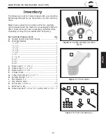
Page 17: ...ench 11 8 1 J Hex Wrench 2mm 1 K Set Screws 1 4 20 x 5 8 12 L Roll Pins 5 x 28 3 M Table Stop Bolt 3 8 16 x 61 2 w Hex Nut 3 8 16 1 Inventory Figure 9 4 Dust chute F Figure 8 Sanding spindles and tabl...

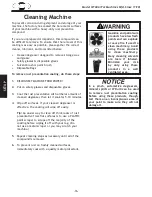
Page 18: ...faces If your cleaner degreaser is effective the coating will wipe off easily Tip An easier way to clean off thick coats of rust preventative from flat surfaces is to use a PLASTIC paint scraper to sc...

Page 19: ...n Physical Environment The physical environment where your machine is operated is important for safe operation and the longevity of its components For best results operate this machine in a dry enviro...

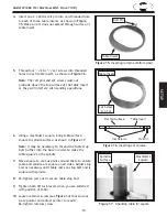
Page 20: ...mble machine do these steps 1 Secure dust chute to trunnion assembly with pre installed 2 3 8 16 x 11 2 hex bolts 3 8 lock washers and 3 8 16 hex nuts see Figure 12 2 Thread 3 8 16 x 61 2 stop bolt an...

Page 21: ...rests on stop bolt and is square with spindle 8 Re tighten jam nut to secure table stop bolt 9 Tighten both tilt lock levers when you are satisfied with position of table 10 Loosen retainer screw see...

Page 22: ...FM recommendation with the rating of the dust collector To determine the CFM at the dust port you must consider these variables 1 CFM rating of the dust collector 2 hose type and length between the du...

Page 23: ...red away from the machine 3 Connect the machine to the power source 4 Verify that the machine is operating correctly by turning it ON When operating correctly the machine runs smoothly with little or...

Page 24: ...FORE using machine To reduce the risk of eye injury and long term respiratory damage always wear safety glasses and a respirator while operating this machine If you are an inexperienced operator we st...

Page 25: ...that any stock you process with the sander is clean and free of dirt nails staples tiny rocks or any other foreign objects that could damage the sanding belt or eject from the workpiece during sandin...

Page 26: ...o the rack with a hex nut To mount spindle for sanding do these steps 1 DISCONNECT MACHINE FROM POWER 2 Determine spindle size needed 3 Lubricate threads and shaft shown in Figure 21 with a light oil...

Page 27: ...avoid increasing the grit number by intervals of more than 50 To change sanding sleeve on spindles larger than 5 8 do these steps 1 DISCONNECT MACHINE FROM POWER 2 Loosen hex nut located on top of spi...

Page 28: ...ill not make contact with the spindle even when the table is tilted 4 Adjust set screws shown in Figure 27 so top of insert is flush with table surface Figure 26 Installing table insert Figure 27 Adju...

Page 29: ...Sanding Sleeve Figure 30 Bevel sanding illustration Note When marking the finish line on your workpiece always mark on the outside or longest edge of the bevel as shown in Figure 30 This allows the f...

Page 30: ...he fixed caster side allows orientation of the wheels in two directions The base can be assembled in any of eight configurations for maximum flexibility Adjusts from 101 2 x 141 2 to 171 2 x 211 2 600...

Page 31: ...instead of having to build an entire fixed dust collection system and running ducts to each machine CSA certified meeting CSA C22 2 243 M91 and UL 1017 4th standards The W1849 14 Resaw Bandsaw is a m...

Page 32: ...ation if you ever observe any of the items below shut down the machine immediately and fix the problem before continuing operations Loose mounting bolts Worn or damaged sanding drums and sleeves Worn...

Page 33: ...will begin to fall off causing deep gouges in the workpiece Glue used to hold the grit to the paper will rub off onto the workpiece causing burns and interfering with the final finish Figure 33 Sandin...

Page 34: ...k 4 Motor overheated 5 Motor at fault 6 Motor bearings at fault 1 Clean sanding sleeve Page 31 2 Replace sanding sleeve Page 25 3 Reduce feed rate workpiece pressure 4 Clean motor let cool and reduce...

Page 35: ...oftwood or wood with a high amount of pitch 3 Sanding sleeve worn or damaged 1 Clean sanding sleeve Page 31 and then reduce feed rate workpiece pressure 2 Use different stock or accept characteristics...

Page 36: ...but it may not match your machine Always use the wiring diagram inside the motor junction box CAPACITORS INVERTERS Some capacitors and power inverters store an electrical charge for up to 10 minutes a...

Page 37: ...240 VAC 6 15 Plug As Recommended Ground Start Capacitor 300uF 125VAC Ground Rewired for 240V Figure 37 ON OFF switch wiring Figure 36 Start capacitor Figure 35 Motor wiring 120V Figure 34 Motor wirin...

Page 38: ...3 Plug power cord into grounded outlet only 4 Do not wear loose clothing gloves or jewelry Roll up or button long sleeves and tie back long hair 5 Do not use when tired or under the influence of drugs...

Page 39: ...GEAR 24T 103 X1686103 HEX BOLT 3 8 16 X 1 1 4 30 X1686030 CONNECTING ROD 104 X1686104 BALL BEARING 6206ZZ 31 X1686031 WRIST PIN 105 X1686105 SEAL 30 62 8 32 X1686032 DRIVE SHAFT 106 X1686106 INT RETA...

Page 40: ...NER 67 X1686067 FLANGE 40 X1686040 SPINDLE 1 2 68 X1686068 FLANGE 41 X1686041 RETAINER 69 X1686069 FLANGE 42 X1686042 SPINDLE 5 8 73 X1686073 SPINDLE HOLDER RIGHT 43 X1686043 RETAINER 74 X1686074 SPIN...

Page 41: ...Model W1686 For Machines Mfd Since 11 10...

Page 42: ...tape along edges please do not staple Fold along dotted lIne Fold along dotted lIne Woodstock international inc p o box 2309 bellingham Wa 98227 2309 place stamp Here...

Page 43: ...he scope of Woodstock International Inc s warranty then the original owner must bear the cost of storing and returning the product This is Woodstock International Inc s sole written warranty and any a...

Page 44: ......

Reviews: