background image

-20-

Model W1704 (For Machines Mfd. Since 01/20)

O

PE

R

ATIO

NS

Workpiece.Inspection

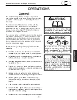
Some workpieces are not safe to turn or may 

require modification before they can be made 

safe to turn.

Before.turning,.get.in.the.habit.of.inspecting.

all.workpieces.for.the.following

:

• 

Material Type:

 This machine is intended 

for turning natural wood products. Never 

attempt to turn any composite wood 

materials, plastics, metal, stone, or rubber 

workpieces; turning these materials can 

lead to machine damage or severe injury

• 

Foreign Objects: 

Nails, staples, dirt, 

rocks and other foreign objects are often 

embedded in wood. While turning, these 

objects can become dislodged and hit the 

operator, cause tool grab, or break the 

turning tool, which might then fly apart. 

Always visually inspect your workpiece for 

these items. If they can't be removed, DO 

NOT turn the workpiece.

•.

Large/Loose Knots:

.

Loose knots can 

become dislodged during the turning 

operation. Large knots can cause a 

workpiece to completely break in half 

during turning and cause machine damage 

and injury. Choose workpieces that do not 

have large/loose knots.

•.

Wet or "Green" Stock:

 Turning wood with 

a moisture content over 20% can cause 

increased wear on tooling.

• 

Excessive Warping:

 Workpieces with 

excessive bowing or twisting are unstable 

and unbalanced. Never turn these 

workpieces at high speed, or instability will 

be magnified and the workpiece can be 

ejected from the lathe causing injury. Only 

turn concentric workpieces!

Summary of Contents for SHOP FOX W1704

Page 1: ...4 3482 Online Technical Support techsupport woodstockint com COPYRIGHT DECEMBER 2003 BY WOODSTOCK INTERNATIONAL INC REVISED JANUARY 2020 MN WARNING NO PORTION OF THIS MANUAL MAY BE REPRODUCED IN ANY SHAPE OR FORM WITHOUT THE WRITTEN APPROVAL OF WOODSTOCK INTERNATIONAL INC 5378TR Printed in China 4000909 ...

Page 2: ...ng grinding tool integrity and the usage of personal protective equipment The manufacturer will not be held liable for injury or property damage from negligence improper training machine modifications or misuse Some dust created by power sanding sawing grinding drilling and other construction activities contains chemicals known to the State of California to cause cancer birth defects or other repr...

Page 3: ...eaning Machine 16 Machine Placement 16 Assembly 17 Test Run 18 OPERATIONS 19 General 19 Workpiece Inspection 20 Selecting Turning Tools 21 Adjusting Tailstock 22 Adjusting Tool Rest 23 Installing Removing Headstock Center 24 Installing Removing Tailstock Center 25 Installing Removing Faceplate 26 Changing Spindle Speed 27 Spindle Turning 28 Faceplate Turning 30 Sanding Finishing 31 ACCESSORIES 32 ...

Page 4: ...hop environment is different Always consider safety first as it applies to your individual working conditions Use this and other machinery with caution and respect Failure to do so could result in serious personal injury damage to equipment or poor work results This machine has been specially designed to provide many years of trouble free service Close attention to detail ruggedly built parts and ...

Page 5: ...Phase 60 Hz Full Load Current Rating 3 2A Minimum Circuit Size 15A Connection Type Cord Plug Power Cord Included Yes Power Cord Length 6 ft Power Cord Gauge 18 AWG Plug Included Yes Included Plug Type 5 15 Switch Type Paddle Safety Switch w Removable Key Motors Main Horsepower 1 3 HP Phase Single Phase Amps 4A Speed 4600 RPM Type Universal Power Transfer Belt Bearings Shielded Permanently Lubricat...

Page 6: ... Tailstock Taper MT 1 Type of Included Tailstock Center Live Construction Bed Precision Ground Cast Iron Frame Cast Iron Steel Headstock Cast Iron Steel Tailstock Cast Iron Steel Paint Type Finish Enamel Other Related Information Bed Width 5 1 8 in Faceplate Size 5 3 4 in Other Country of Origin China Warranty 2 Years Approximate Assembly Setup Time 15 Minutes Serial Number Location ID Label on La...

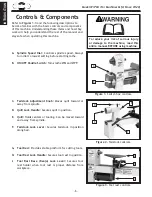
Page 7: ...tion b Do not wear gloves necktie or loose clothing c Tighten all locks before operating d Rotate workpiece by hand before applying power e Rough out workpiece before installing on faceplate f Do not mount split workpiece or one containing knot g Use lowest speed when starting new workpiece Quill Bed Tool Rest Motor ON OFF Switch Headstock Spindle Tailstock Adjustment Knob Spindle Speed Dial Tool ...

Page 8: ...e speed Always turn dial to lowest setting before starting lathe B ON OFF Paddle Switch Turns lathe ON and OFF C Tailstock Adjustment Knob Moves quill toward or away from spindle D Quill Lock Handle Secures quill in position E Quill Holds centers or tooling Can be moved toward and away from spindle F Tailstock Lock Lever Secures tailstock in position along bed G Tool Rest Provides stable platform ...

Page 9: ...s or alcohol when tired or when distracted ELECTRICAL EQUIPMENT INJURY RISKS You can be shocked burned or killed by touching live electrical components or improperly grounded machinery To reduce this risk only allow an electrician or qualified service personnel to do electrical installation or repair work and always disconnect power before accessing or exposing electrical equipment DISCONNECT POWE...

Page 10: ...uce accidental contact with moving parts or flying debris make sure they are properly installed undamaged and working correctly FORCING MACHINERY Do not force machine It will do the job safer and better at the rate for which it was designed NEVER STAND ON MACHINE Serious injury may occur if machine is tipped or if the cutting tool is unintentionally contacted STABLE MACHINE Unexpected movement dur...

Page 11: ... it through its entire range of motion EYE FACE PROTECTION Always wear a face shield and safety glasses when operating lathe PROPER APPAREL Do not wear gloves necktie or loose clothing Keep keep long hair away from rotating spindle SPEED RATES Select correct spindle speed for workpiece size type shape and condition Use low speeds when roughing or when turning large long or non concentric workpiece...

Page 12: ...s for operat ing the lathe Offset Turning A turning situation where the center of the workpiece is offset at various stages of the work to produce different shapes Outboard Turning Turning of workpiece with the headstock situated at the far end of the lathe so the work done is not over the bed of the lathe Roughing Out Taking stock from square billet to round blank Spindle This term has two meanin...

Page 13: ...Circuit Type 110V 120V 60 Hz Single Phase Circuit Size 15 Amps Plug Receptacle NEMA 5 15 Full Load Current Rating The full load current rating is the amperage a machine draws at 100 of the rated output power On machines with multiple motors this is the amperage drawn by the largest motor or sum of all motors and electrical devices that might operate at one time during normal operations Full Load C...

Page 14: ...ew one For 120V Connection Extension Cords We do not recommend using an extension cord with this machine Extension cords cause voltage drop which may damage electrical components and shorten motor life Voltage drop increases with longer extension cords and smaller gauge sizes higher gauge numbers indicate smaller sizes Any extension cord used with this machine must contain a ground wire match the ...

Page 15: ...nal injury may occur Wear safety glasses during entire setup process This machine presents serious injury hazards to untrained users Read through this entire manual to become familiar with the controls and opera tions before starting the machine Items Needed for Setup The following items are needed but not included to set up your machine Description Qty Safety Glasses for each person 1 Solvent Cle...

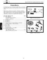
Page 16: ...packaging materials while unpacking or they are pre installed at the factory Inventory Figures 5 6 Qty A Lathe Assembly Tool Rest Base mounted 1 Tailstock mounted 1 B Faceplate 53 4 1 C Tool Rest 7 1 D Tool Rest 41 2 1 E Adjustable Levers Tool Rest Base Tailstock 2 F Lock Handle M6 1 x 28 Tool Rest 1 G Live Center 1 H Spur Center 1 I Knockout Tool 1 J Lock Handle M6 1 x 17 Quill 1 K Hardware Not S...

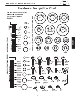
Page 17: ...S ARE 1MM APART 5mm 10mm 20mm 15mm 25mm 40mm 30mm 35mm 45mm 50mm 60mm 55mm 70mm 65mm 75mm W A S H ER DIAM E T E R 5 8 W A S H ER DIAM E T E R 9 16 1 2 W A S H ER DIA M E T E R W A S H ER DIA M E T E R 12mm W A S H E R DIA M E T E R 10mm 7 16 W A S H ER DIA M E T E R W A S H E R DIA M E T E R 8mm 3 8 W A S H E R DIA M E T E R 5 16 W A S H E R DIA M E T E R 1 4 W A S H E R DIA M E T E R 10 W A S H E...

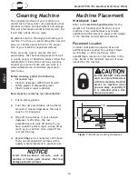
Page 18: ...e time you spend doing this now will give you a better appreciation for the proper care of your machine s unpainted surfaces There are many ways to remove this rust preventative but the following steps work well in a wide variety of situations Always follow the manufacturer s instructions with any cleaning product you use and make sure you work in a well ventilated area to minimize exposure to tox...

Page 19: ... M6 1 x 17 quill lock handle as shown in Figure 8 2 Install tool rest base lock lever and M6 1 x 28 tool rest lock handle as shown in Figure 9 3 Insert tool rest into tool rest base and tighten tool rest lock handle see Figure 10 Note Unless workpiece clearance is an issue always install the larger of the 2 tool rests included with this machine to give yourself more room to work lock levers Figure...

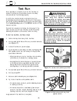
Page 20: ...peed dial all the way counterclockwise see Figure 11 3 Connect machine to power supply 4 Verify machine is operating correctly by flipping ON OFF paddle switch up then slowly turning spindle speed dial clockwise When operating correctly machine runs smoothly with little or no vibration or rubbing noises Investigate and correct strange or unusual noises or vibrations before operating machine furthe...

Page 21: ...ool rest to 1 4 gap 5 Rotates workpiece by hand to verify spindle and workpiece rotate freely through full range of motion 6 Verifies spindle speed dial is turned all the way counterclockwise so spindle does not start in high speed 7 Puts on safety glasses face shield and respirator 8 Turns lathe ON adjusts lathe speed and carefully begins turning operation keeping chisel against tool rest entire ...

Page 22: ...become dislodged and hit the operator cause tool grab or break the turning tool which might then fly apart Always visually inspect your workpiece for these items If they can t be removed DO NOT turn the workpiece Large Loose Knots Loose knots can become dislodged during the turning operation Large knots can cause a workpiece to completely break in half during turning and cause machine damage and i...

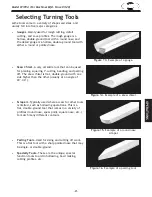
Page 23: ...Example of a parting tool Parting Tools Used for sizing and cutting off work This is a flat tool with a sharp pointed nose that may be single or double ground Specialty Tools These are the unique special function tools to aid in hollowing bowl making cutting profiles etc Scrapers Typically used where access for other tools is limited such as hollowing operations This is a flat double ground tool t...

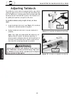
Page 24: ...s lock nut in small increments to fine tune the clamping pressure as needed Figure 18 Location of tailstock clamp nut Tailstock Clamp Bolt Always operate lathe with tailstock firmly locked to bed Otherwise serious personal injury may occur by tailstock moving during operation and workpiece being ejected at high speed The tailstock on this lathe is equipped with a cam action clamping system to secu...

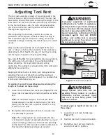
Page 25: ...upported or positioned cutting tools can catch on workpiece ejecting tool from your hands with great force To reduce this risk always ensure tool rest is properly positioned for each type of operation cutting tool is firmly supported against tool rest BEFORE cutting and cutting tool is properly positioned to cut at the correct angle for tool and operation type To position tool rest forward backwar...

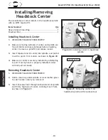
Page 26: ...ck firm motion as shown in Figure 20 4 Make sure center is securely installed by attempting to pull it out by hand a properly installed center will not pull out easily Figure 20 Installing center in headstock spindle Headstock Spindle Center Removing Headstock Center 1 DISCONNECT MACHINE FROM POWER 2 Hold a clean rag under spindle or wear leather glove to catch center when you remove it 3 Insert k...

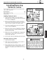
Page 27: ...igned with quill keyway to ensure center and quill will not freely rotate under load 6 Secure quill in place by tightening quill lock handle Removing Tailstock Center 1 Loosen quill lock handle 2 Hold a clean rag under spindle or wear a glove to catch center when you remove it 3 Rotate adjustment knob counterclockwise quill will retract back into tailstock causing center to be forced out If necess...

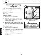
Page 28: ...g Faceplate 1 DISCONNECT MACHINE FROM POWER 2 Put open end of wrench over flats behind faceplate While holding spindle in place with knockout rod turn wrench counterclockwise until faceplate is removed see Figure 24 Note If spur center is installed it will be removed during this process Installing Faceplate 1 DISCONNECT MACHINE FROM POWER 2 While holding spindle in place thread faceplate clockwise...

Page 29: ...r 2 1520 3200 3200 2 4 760 1600 2480 4 6 510 1080 1650 6 8 380 810 1240 8 10 300 650 1000 10 12 255 540 830 12 14 220 460 710 Figure 25 Typical spindle speed recommendations Changing Spindle Speed Always choose correct spindle speed for an operation Using wrong speed may lead to workpiece being thrown at high speed causing fatal or severe impact injuries Figure 26 Location of spindle speed dial Sp...

Page 30: ... from corner to corner across end of workpiece as shown in Figure 28 2 Make a center mark by using a wood mallet and tapping point of spur center into center of workpiece on both ends 3 Using a 1 4 drill bit drill a 1 4 deep hole at center mark on end of the workpiece to be mounted on headstock spur center 4 To help embed spur center into workpiece cut 1 8 deep saw kerfs in headstock end of workpi...

Page 31: ... until the spindle reaches full speed and you can verify that the workpiece will not come loose Use the slowest speed when starting or stopping the lathe Select the right speed for the size of workpiece that you are turning refer to Figure 25 on Page 27 Keep the turning tool on the tool rest the ENTIRE time that it is in contact with the workpiece Learn the correct techniques for each tool you wil...

Page 32: ... during operation Correct Incorrect Figure 33 Correct and incorrect screw types 3 Thread and secure faceplate onto headstock spindle refer to Installing Faceplate on Page 26 If wood screws cannot be placed in workpiece faceplate can be mounted to a backing block attached to workpiece see Mounting the Workpiece to a Backing Block 1 Make backing block from a suitable size piece of scrap wood Note Fa...

Page 33: ...wn in Figure 34 Note Whenever sanding or finishing move the tool rest holder out of the way to increase personal safety and gain adequate working room Figure 34 Typical sanding operation Wrapping sandpaper completely around workpiece could pull your hands into moving workpiece and may cause serious injury Never wrap sandpaper or finishing materials completely around workpiece Sandpaper Workpiece ...

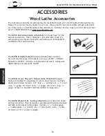
Page 34: ...D2304 Steelex Plus 6 Pc Deluxe Lathe Chisel Set features beefy ash handles for unsurpassed control brass ferrules and high speed steel blades Includes a 17 long 13 16 parting tool 13 16 round nose 3 8 gouge 19 long 1 skew 5 8 gouge and a 223 4 long 3 8 gouge Comes in a beautiful red blow molded carrying case The D2250 Steelex 5 Pc Turning Chisel Set is for those fine detail turning operations This...

Page 35: ...ofiles include 1 8 1 4 5 16 and 3 8 diameters Tapered sides allow closely spaced multiple beads for complete design flexibility Naturally finished ash handles measure 87 8 and the high speed steel blades measure 51 8 long the 1 8 beaded chisel blade measures 4 long Find the center of round or square stock for lathe turning with the D3098 Center Finder One side locates a diagonal line on square sto...

Page 36: ...ow any oil to get on the inside mating surfaces of the spindle Use the tailstock adjustment knob to extend the quill out to the furthest position and apply a thin coat of white lithium grease to the outside of the quill DO NOT allow any oil or grease to get on the inside mating surfaces of the quill MAKE SURE that your machine is unplugged during all maintenance procedures If this warning is ignor...

Page 37: ...ned at the factory and should not require any adjustment If they become misaligned over time it is important that they be re aligned in order to extend belt life and maximize the transfer of power from the motor to the spindle Tools Needed Qty Phillips Head Screwdriver 2 1 Hex Wrench 3mm 1 To align motor and spindle pulleys do these steps 1 DISCONNECT MACHINE FROM POWER 2 Remove outboard spindle c...

Page 38: ...ing plate cap screws and apply downward pressure on motor assembly to properly tension drive belt then re tighten cap screws Note When properly tensioned belt should deflect about 1 8 when moderate pressure is applied to belt mid way between upper and lower pulley as illustrated in Figure 38 8 Ensure belt is fully seated on pulleys roll machine upright if necessary and re install outboard spindle ...

Page 39: ...tion of fuse holder Fuse Holder Replacing Brushes This machine is equipped with a universal motor that uses two carbon brushes to transmit electrical current inside the motor These brushes are considered to be regular wear items or consumables that will need to be replaced during the life of the motor The frequency of required replacement is related to how much the motor is used and how hard it is...

Page 40: ... at fault 8 Remove replace brushes Page 37 9 Reset circuit breaker inspect replace if at fault 10 Inspect replace if at fault 11 Test repair replace Machine stalls or is underpowered 1 Machine undersized for task 2 Workpiece material not suitable for machine 3 Feed rate cutting speed too fast 4 Belt slipping 5 Pulley slipping on shaft 6 Spindle speed dial at fault 7 Motor brushes worn or at fault ...

Page 41: ...e wobble 4 Reduce spindle speed Page 27 5 Stop lathe and fix interference problem 6 Check lock levers and handles and tighten if nec essary Page 17 7 Align belt pulleys Page 35 8 Tighten motor mount bolts 9 Replace belt Page 36 10 Test by rotating shaft rotational grinding loose shaft requires bearing replacement Chisel grabs or digs into workpiece 1 Wrong chisel tool being used 2 Chisel tool too ...

Page 42: ... but it may not match your machine Always use the wiring diagram inside the motor junction box CAPACITORS INVERTERS Some capacitors and power inverters store an electrical charge for up to 10 minutes after being disconnected from the power source To reduce the risk of being shocked wait at least this long before working on capacitors CIRCUIT REQUIREMENTS You MUST follow the requirements at the beg...

Page 43: ... 41 Model W1704 For Machines Mfd Since 01 20 SERVICE Electrical Components Figure 41 Switch box wiring and components Power Cord Spindle Speed Dial Fuse Holder ON OFF Switch Circuit Board Motor Cord ...

Page 44: ...Wt Wt Gn Gn Gn Ground Gn CIRCUIT BOARD VARIABLE SPEED DIAL MOTOR Bk Wt Bk Wt Wt Wt Wt Gn Bk Wt FUSE 10A Bk The motor wiring shown here is current at the time of printing but it may not match your machine Always use the wiring diagram inside the motor junction box SHOCK HAZARD Disconnect power before working on wiring STOP Read Page 40 Before Wiring ...

Page 45: ...S Main 2 3 4 5 6 7 8V2 9 10 11 14 15 16 17 18 19 20 21 22 23 24 25 26 27 28 29 30V2 31 32 33 34 35 36V2 37 38 39 40 41V2 42V2 43 44 45 46 47 48 49 50 51 52 53 54 55 56 57 58 59 60 61 62 64 65 70 72 73 74 76 1 24 50A 7 1 73 68 1 68 68A 75 71 77 41V2 1 41V2 2 ...

Page 46: ...EL 22 X1704022 BALL BEARING 6004ZZ 58 X1704058 SHOP FOX PADDLE SWITCH 23 X1704023 HEADSTOCK 59 X1704059 FUSE 10A 24 X1704024 LOCK NUT M8 1 25 60 X1704060 SPINDLE SPEED DIAL SWITCH 25 X1704025 SPEED DIAL LABEL 61 X1704061 FLAT WASHER 6MM 26 X1704026 HEADSTOCK SPINDLE NUT 62 X1704062 LOCK WASHER 6MM 27 X1704027 OUTBOARD SPINDLE COVER 64 X1704064 PHLP HD SCR M4 7 X 10 28 X1704028 PHLP HD SCR M4 7 X 8...

Page 47: ...turning the product This is Woodstock International Inc s sole written warranty and any and all warranties that may be implied by law including any merchantability or fitness for any particular purpose are hereby limited to the duration of this written warranty We do not warrant that Shop Fox machinery complies with the provisions of any law acts or electrical codes We do not reimburse for third p...

Page 48: ......

Reviews: