background image

-60-

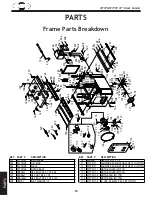
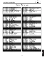
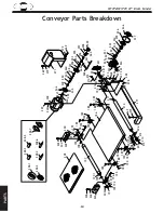
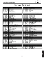
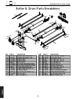
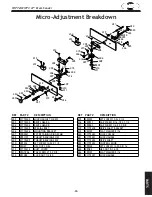
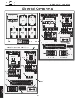
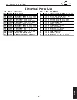
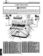
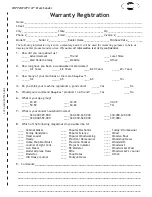
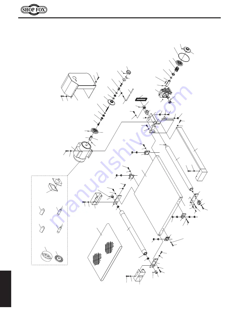
W1772/W1773 37" Drum Sander

PA

RT

S

Conveyor Parts Breakdown

���

���

���

���

���

���

���

���

���

���

���

���

���

���

���

���

���

���

���

���

���

���

���

���

���

���

���

���

���

�����

���

���

���

���

���

���

���

���

���

���

���

���

���

���

���

���

���

���

���

���

���

���

���

���

���

���

���

���

���

���

���

���

���

���

���

��� ���

���

���

���

���

���

���

���

���

���

���

���

���

�����

�����

�����

�����

�����

�����

�����

���

���

���

���

���

���

���

���

���

���

���

���

���

���

���

���

���

���

���

���

���

���

���

���

���

���

���

���

���

���

���

���

���

���

���

���

���

Summary of Contents for SHOP FOX W1772

Page 1: ...82 Online Technical Support tech support shopfox biz COPYRIGHT OCTOBER 2007 BY WOODSTOCK INTERNATIONAL INC WARNING NO PORTION OF THIS MANUAL MAY BE REPRODUCED IN ANY SHAPE OR FORM WITHOUT THE WRITTEN...

Page 2: ......

Page 3: ...able Speed 24 Using the Amp Draw Meter 25 Sanding 25 Sanding Tips 26 Choosing Sandpaper 27 Paper Replacement 28 Drum Sander Accessories 29 MAINTENANCE 30 General 30 Cleaning 30 Lubrication 30 SERVICE...

Page 4: ...ration maintenance and service of this product We stand behind our machines In the event that questions arise about your machine please contact Woodstock International Technical Support at 360 734 348...

Page 5: ...3 W1772 W1773 37 Drum Sander INTRODUCTION...

Page 6: ...4 W1772 W1773 37 Drum Sander INTRODUCTION...

Page 7: ...5 W1772 W1773 37 Drum Sander INTRODUCTION...

Page 8: ...6 W1772 W1773 37 Drum Sander INTRODUCTION...

Page 9: ...r Lock Knob I Table Height Lock Knob J Dust Port K Top Cover Handle L Rear Drum M Front Drum N Gas Strut O Pressure Roller P Emergency Stop Bar Q Top Cover R Lifting Hook S Control Panel See Page 23 T...

Page 10: ...moving parts Wear protective hair covering to contain long hair and wear non slip footwear 6 NEVER OPERATE MACHINERY WHEN TIRED OR UNDER THE INFLUENCE OF DRUGS OR ALCOHOL Be mentally alert at all time...

Page 11: ...ng for keys and adjusting wrenches before turning machinery ON 18 CHECK FOR DAMAGED PARTS BEFORE USING MACHINERY Check for binding and alignment of parts broken parts part mounting loose bolts and any...

Page 12: ...out an adequate dust collection system in place and running 8 BE ATTENTIVE Never leave the machine running unattended 9 REPLACING SANDING PAPER Replace sanding paper when it becomes worn or damaged 10...

Page 13: ...a permanent installation with conduit runs this task can only be safely accomplished by a quali fied electrician As always observe all applicable electri cal codes when connecting this machine to powe...

Page 14: ...ower source Figure 3 Locking shutoff switch Voltage Amp Draw Min Circuit Size Connection Cord Extension Cord 220V 44 3 60A Hardwire Conduit Setup N A Hardwire Only 440V 22 15 30A Hardwire Conduit Setu...

Page 15: ...awings in the junction box cover as they will reflect any changes to the machine since the time of writing 3 Open the control panel and familiarize yourself with Figure 75 on Page 50 for component loc...

Page 16: ...you do any assembly or adjust ment tasks Otherwise serious per sonal injury to you or others may occur OFF SUFFOCATION HAZARD Immediately discard all plastic bags and pack ing materials to elimi nate...

Page 17: ...nd of each strut should be flush with the outside of the bracket 4 Close the top cover remove the cap screws securing the pulley cover and open the cover 5 Pull the V belt down to rotate the sanding d...

Page 18: ...panel into place and secure it with the bolts flat washers and hex nuts removed in Step 7 10 Reinstall the right access panel 11 Attach the brace from the control panel to the sander as shown in Figur...

Page 19: ...existing and anticipated needs size of material to be processed through the machine and space for auxiliary stands work tables or other machinery when establishing a location for your drum sander see...

Page 20: ...ich may cause a tripping hazard if you decide to move your machine at a later point Bolting to Wood Floors The most secure method of mounting this drum sander to a wood floor is using 3 8 hex bolts wi...

Page 21: ...t pro duces a minimum of 2000 CFM A fine layer of dust will be present on your stock as it comes out of the sander This is normal To connect the dust ports to a dust collector do these steps 1 Attach...

Page 22: ...URCE CIRCUIT BREAKER and attach the wires to the locking shutoff switch Gear Oil Check It is important to make sure the gear box has adequate oil in it before running the sander for the first time to...

Page 23: ...nder do these steps 1 Make sure you understand the safety instructions at the beginning of the manual and verify that the machine is setup properly 2 Make sure the feed motor gearbox is full of oil an...

Page 24: ...e criteria below If the drums rotate toward the back of the machine they are moving in the cor rect direction If the drums rotate toward the front of the machine they are moving in the wrong direction...

Page 25: ...eyond the scope of this manual Many of these operations can be dangerous or deadly if performed incorrectly The instructions in this section are written with the under standing that the operator has t...

Page 26: ...on veyor table until the workpiece makes light contact with the sanding drums This is the correct height to begin sanding the workpiece Figure 24 Table height handwheel Variable Speed The variable spe...

Page 27: ...severe personal injury Close all covers and panels before starting the drum sander Failure to do so could result in severe personal injury Using the Amp Draw Meter The amp draw meter Figure 26 is use...

Page 28: ...oards less than 9 long or less than 1 16 to prevent damage to the workpiece and the drum sander Extend the life of the sandpaper by regularly using a PRO STICK sanding pad Page 29 When sanding workpie...

Page 29: ...remove the scratches from the previous grit The Model W1772 W1773 allows you to place a differ ent grit sandpaper on each drum The front drum should have a coarser grit than the rear Usually this tran...

Page 30: ...ee Figure 31 if using a dif ferent width of sandpaper 7 Start with the left side of the drum fold the corner of the sandpaper into the spring clip then install the clip onto the tension wheel Tap the...

Page 31: ...sults Model Grit Use D3881 60 Thickness sanding glue removal D3882 80 Removing planer marks and initial finish sanding D3883 100 Removing planer makrs and initial finish sanding D3884 120 Finish sandi...

Page 32: ...easy From time to time vacuum wood dust off of the internal compo nents especially the motor Cleaning Lubrication Moving parts such as chains should be lubricated peri odically with a light machine o...

Page 33: ...loosen the four hex bolts Figure 34 that secure the gear box to the motor bracket and remove the V belt 3 With the oil and gearbox warm slide the gearbox out remove the fill plug Figure 34 remove the...

Page 34: ...cabinet for future use To make the gauge blocks do these steps 1 Edge joint the concave edge of a 7 long 2x4 flat on a jointer as shown in Figure 37 2 Place the jointed edge of the 2x4 against the tab...

Page 35: ...the direction shown in Figure 40 to loosen or tighten the V belts 4 Close the pulley cover and reinstall the handwheel Removal Replacement Replace the V belt if you notice fraying cracking glaz ing or...

Page 36: ...ey are all coplanar with each other 6 Close the pulley cover and reinstall the handwheel Figure 41 Checking pulley alignment with a straightedge OFF Figure 42 Pillow bearing mounting nuts washers and...

Page 37: ...earing Housing Grease Groove Grease Port 9 Insert the new bearing into the bearing housing so the set screws and hub are on the same side as the grease Zerk on the bearing housing Figures 42 and 46 10...

Page 38: ...veyor Your goal is to reach a 3 4 gap between the underside of the conveyor and the belt as shown in Figure 48 3 Use a magic marker white out or fingernail polish to mark the front of the conveyor ten...

Page 39: ...middle and stays there during continuous operation To track the conveyor do these steps 1 Make sure the drums are perpendicular to the feed direction parallel with the conveyor roller Go to Page 38 2...

Page 40: ...ds parallel to the conveyor rollers they may put a side load on the conveyor belt during operation forcing the conveyor to track off to the side and possibly causing damage To adjust the drums perpend...

Page 41: ...e next step 9 Make two gauge blocks the same width as your mea surement in Step 8 10 Place the small gauge blocks on each end of the pressure roller between both drums as shown in Figure 53 11 Loosen...

Page 42: ...54 is critical to the sand ing operation Take care to adjust the drums parallel to the conveyor surface within 0 002 from one side to the other To adjust the rear drum height and adjust the drums para...

Page 43: ...the additional 0 007 to 0 015 height from Step 12 See Figure 58 Some trial and error may be needed to find the optimal setting based upon the sandpaper grit size you use ie coarse grit smaller number...

Page 44: ...pressure on the rear rollers but not the front rollers Conditions will vary with wood types so use trial and error to find the best results for your application These instructions will restore the pre...

Page 45: ...re than allowed at the pillow bearing adjustments or if you have removed the table or chain during a service procedure and you need to reset the drums parallel to the table Figure 61 Scale pointer scr...

Page 46: ...least the 1 mark on the height scale 4 At the lift screw that needs to be adjusted mark the end of a sprocket tooth and the chain hole where that tooth is meshed as shown in Figure 63 5 Using two 14m...

Page 47: ...stop bar limit switch ELECTRICAL BOX W1772 220 1 Ph see Pages 47 48 W1773 220V 3 Ph see Pages 50 51 440V 3 Ph see Pages 52 53 FEED MOTOR W1772 see Page 49 W1773 see Page 55 SANDING DRUM MOTOR W1772 s...

Page 48: ...72 W1773 37 Drum Sander SERVICE W1772 W1773 Control Panel Figure 67 W1772 W1773 control panel W1772 220V 1 Ph Page 48 W1773 220 3 Ph Page 51 W1773 440V 3 Ph Page 53 Figure 66 W1772 W1773 control panel...

Page 49: ...trical Box 220V 1 Ph Figure 68 W1772 electrical box Current Sensor Ground OFF Feed Motor Contactor Feed Motor Relay dial 2 7A Sanding Motor Relay dial 43A Sanding Motor Contactor Incoming Power Termin...

Page 50: ...nder SERVICE W1772 Electrical Box Wiring 220V 1 Ph To Sanding Drum Motor Figures 69 70 73 To Feed Motor Figures 71 72 74 To Emerg Stop Bar Limit Switch Figure 65 To Control Panel Figures 66 67 Incomin...

Page 51: ...W1772 sanding drum motor wiring and start capacitors Figure 70 W1772 sanding drum motor run capacitors Figure 71 W1772 feed motor wiring Figure 72 W1772 feed motor capacitors Figure 73 W1772 sanding...

Page 52: ...0V 3 Phase Figure 75 W1773 220V 3 phase electrical box wiring OFF Feed Motor Contactor Current Sensor Feed Motor Relay dial 1 3A Control Panel Terminal Block av Sanding Motor Relay dial 43A Incoming P...

Page 53: ...rum Sander SERVICE W1773 Electrical Box Wiring 220V 3 Phase Incoming 220V Three Phase Power To Sanding Drum Motor Figure 77 To Feed Motor Figure 79 To Emerg Stop Bar Limit Switch Figure 65 To Control...

Page 54: ...e Figure 76 W1773 440V 3 phase electrical box wiring Sanding Motor Contactor Feed Motor Contactor Amp Meter Transformer Current Sansor OFF Feed Motor Relay dial 0 65A Control Panel Terminal Block av S...

Page 55: ...37 Drum Sander SERVICE W1773 Electrical Box Wiring 440V 3 Phase 440 Three Phase Power To Sanding Drum Motor Figure 77 To Feed Motor Figure 80 To Emerg Stop Bar Limit Switch Figure 65 To Control Panel...

Page 56: ...772 W1773 37 Drum Sander SERVICE W1773 Sanding Drum Motor Figure 77 W1773 220V sanding drum motor wiring Figure 78 W1773 440 sanding drum motor wiring W1773 220 3 Phase Page 51 or W1773 440V 3 Phase P...

Page 57: ...55 W1772 W1773 37 Drum Sander SERVICE W1773 Feed Motor Figure 79 W1773 220V feed motor wiring Figure 80 W1773 440 feed drum motor wiring W1773 220 3 Ph Page 51 or W1773 440V 3 Ph Page 53...

Page 58: ...if faulty 8 Check for broken wires or disconnected corroded connections and repair replace as necessary 9 Free push panel from binding replace faulty switch 10 Test repair replace Machine stalls or i...

Page 59: ...One of the sanding drums is not par allel with the table 1 Adjust the sanding drums parallel to the table Page 38 Excessive snipe 1 Too much pressure roller pressure 2 Too much pressure from rear pres...

Page 60: ...R 10HP 1PH W1772 103 X1772103 SCALE 111 X1773111 SANDING DRUM MOTOR 15HP 3PH W1773 105 X1772105 MOTOR BASE 111 1 X1772111 1 MOTOR COVER W1772 106 XPB75M HEX BOLT M12 1 75 X 35 111 1 X1773111 1 MOTOR C...

Page 61: ...30 X1772130 MOUNTING BRACKET 303 X1772303 STRAIN RELIEF 132 X1772132 SHUT OFF BAR 304 X1772304 STRAIN RELIEF 133 XPSBS09M BUTTON HD CAP SCR M6 1 X 12 305 X1772305 CABLE CLAMP 135 X1772135 COMPRESSION...

Page 62: ...60 W1772 W1773 37 Drum Sander PARTS Conveyor Parts Breakdown...

Page 63: ...12M KEY 5 X 5 X 55 204 XPW06 FLAT WASHER 1 4 242 XPN03M HEX NUT M8 1 25 205 X1772205 CONVEYOR BELT 243 X1772243 SHAFT 206 X1772206 ROLLER SUPPORT BRACKET 244 XPSS16M SET SCREW M8 1 25 X 10 207 X177220...

Page 64: ...X 40 294 XPW02 FLAT WASHER 3 8 282 1 X1772282 1 LEFT PAPER TENSIONING WHEEL 295 XPLN05M LOCK NUT M10 1 5 282 2 X1772282 2 RIGHT PAPER TENSIONING WHEEL 296 X1772296 SANDING DRUM PULLEY 283 XPR84M EXT...

Page 65: ...DRIVE SHAFT BRACKET 406 X1772406 MOUNTING BRACKET 419 XPW07 FLAT WASHER 5 16 407 XPR09M EXT RETAINING RING 20MM 420 X1772420 LOCK COLLAR 408 XP51101 THRUST BEARING 51101 421 X1772421 LOCK HANDLE 409...

Page 66: ...64 W1772 W1773 37 Drum Sander PARTS Electrical Components...

Page 67: ...TRIC PANEL W1773 440V 543A X1773543A OL RELAY SDE RA 30 19 26 W1773 440V 556 X1772556 CONTROL PANEL PLATE 544 X1772544 CONTACTOR SDE MA 09 220V W1772 559 X1772559 DIGITAL AMP METER 544 X1772544 CONTAC...

Page 68: ...602 X1772602 FEED ONLY ONE LABEL 612 X1772612 SHOP FOX LOGO PLATE 603 X1772603 HAND PINCH IN BELT LABEL 612 1 X1772612 1 LOGO SCREW 604 X1772604 KEEP DOOR CLOSED 613 X1772613 DECORATIVE STRIPE TAPE 60...

Page 69: ...o 5 Would you recommend Shop Fox products to a friend _____ Yes ____ No 6 What is your age group _____ 20 29 ____ 30 39 ____ 40 49 _____ 50 59 ____ 60 69 ____ 70 7 What is your annual household income...

Page 70: ...TAPE ALONG EDGES PLEASE DO NOT STAPLE FOLD ALONG DOTTED LINE FOLD ALONG DOTTED LINE WOODSTOCK INTERNATIONAL INC P O BOX 2309 BELLINGHAM WA 98227 2309 Place Stamp Here...

Page 71: ...of Woodstock International Inc s warranty then the original owner must bear the cost of storing and returning the product This is Woodstock International Inc s sole written warranty and any and all w...

Page 72: ......

Reviews: