background image

�����������������������������������������������������������������������

��������������������������������������������������������������

����������������������������������������������������������������������

��������������������������������������������������������������������

������������������������

�����������������������������������������������������������������������

������������������������������������������������������������������������

�������������������������������������������������������������������

�����������������������������������������������������������������

����������������������������������������������������������������������

�����������������������������������������������

����������������������������������������������������������������

��������������������������������������������������������������������

�������

��������������������������������������������������������������������

�����������������������������������������������������������������������

����������������������������������������������������������������������

�������������������������������������

�� ����������������������������

�� ������������������������������������������������������������������

�� ����������������������������������������������������

������������������������������������������������������������������

������������������������������������������������������������������

��������������������������������������������������������������������

���������������������������������������������������������������������

��������������������������

Summary of Contents for SHOP FOX W1808

Page 1: ...482 Online Technical Support tech support shopfox biz COPYRIGHT MAY 2007 BY WOODSTOCK INTERNATIONAL INC WARNING NO PORTION OF THIS MANUAL MAY BE REPRODUCED IN ANY SHAPE OR FORM WITHOUT THE WRITTEN APPROVAL OF WOODSTOCK INTERNATIONAL INC Printed in Taiwan 9173BL W1808 W1809 W1810 ...

Page 2: ... ...

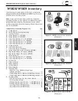
Page 3: ...n Cords 13 Electrical Specifications 13 SETUP 14 Unpacking 14 Items Needed for Setup 14 W1808 W1809 Inventory 15 W1810 Inventory 17 Assembly 19 Test Run 27 OPERATIONS 28 General 28 Remote Control 29 Duct Material 29 System Design 31 System Grounding 36 Cyclone Dust Collector Accessories 37 SERVICE 39 General 39 Emptying Drum 39 Cleaning Filter 39 W1808 Electrical Components 40 W1808 Wiring Diagram...

Page 4: ...on for safety setup operation maintenance and service of this product We stand behind our machines In the event that questions arise about your machine please contact Woodstock International Technical Support at 360 734 3482 or send e mail to tech support shopfox biz Our knowledgeable staff will help you troubleshoot problems and process warranty claims INTRODUCTION If you need the latest edition ...

Page 5: ... 3 W1808 W1809 W1810 Cyclone Dust Collectors INTRODUCTION ...

Page 6: ... 4 W1808 W1809 W1810 Cyclone Dust Collectors INTRODUCTION ...

Page 7: ... 5 W1808 W1809 W1810 Cyclone Dust Collectors INTRODUCTION ...

Page 8: ... 6 W1808 W1809 W1810 Cyclone Dust Collectors INTRODUCTION ...

Page 9: ... 7 W1808 W1809 W1810 Cyclone Dust Collectors INTRODUCTION ...

Page 10: ... 8 W1808 W1809 W1810 Cyclone Dust Collectors INTRODUCTION ...

Page 11: ...ODUCTION Controls and Features A Noise Reducer B Canister Filters C Cartridge Filter Collection Drum D Stand E Collection Drum F Remote Magnetic Switch G Cyclone Funnel H Inlet I Blower Housing J Motor Figure 1 W1810 identificaiton A B C D F G H I E J ...

Page 12: ...aught in moving parts Wear protective hair covering to contain long hair and wear non slip footwear 6 NEVER OPERATE MACHINERY WHEN TIRED OR UNDER THE INFLUENCE OF DRUGS OR ALCOHOL Be mentally alert at all times when running machinery 7 ONLY ALLOW TRAINED AND PROPERLY SUPERVISED PERSONNEL TO OPERATE MACHINERY Make sure operation instructions are safe and clearly understood 8 KEEP CHILDREN AND VISIT...

Page 13: ...of checking for keys and adjusting wrenches before turning machinery ON 18 CHECK FOR DAMAGED PARTS BEFORE USING MACHINERY Check for binding and alignment of parts broken parts part mounting loose bolts and any other conditions that may affect machine operation Repair or replace damaged parts 19 USE RECOMMENDED ACCESSORIES Refer to the instruction manual for recommended accessories The use of impro...

Page 14: ...ng on the dust collector ducting system 4 SUSPENDED DUST PARTICLES AND IGNITION SOURCES Do not operate the dust collector in areas where explosion risks would be high if dust were dispersed into the area Areas of high risk include but are not limited to areas near pilot lights and or open flames 5 EMPTYING DUST When emptying dust from the collection bags or drum wear a respirator and safety glasse...

Page 15: ...e breaker plug receptacle with a verified ground using the recommended circuit size and plugs receptacles listed at the bottom of this page Never replace a circuit breaker with one of higher amperage without consulting a qualified electrician to ensure compliance with wiring codes This machine must be grounded Verify the ground before connecting this machine to the power source If you are unsure a...

Page 16: ...any missing parts find the part number in the back of this manual and contact Woodstock International Inc at 360 734 3482 or at tech support shopfox biz SUFFOCATION HAZARD Immediately discard all plastic bags and pack ing materials to elimi nate choking suffocation hazards for children and animals Items Needed for Setup The following items are needed to complete the set up process but are not incl...

Page 17: ...1 H Collection Drum Lid 1 I Collection Drum 35 Gallon 1 J Upper Collection Drum 25 Gallon W1809 1 K Bag Holder Plates 35 Gallon W1808 4 K Bag Holder Plates 55 Gallon W1809 4 L Hose Clamps 9 2 M Clear Flexible Hose 9 x 7 W1808 1 M Clear Flexible Hose 9 x 13 W1809 1 N Outlet Port 1 O Filter L Braces 2 P Barrel Gaskets 2 Q Outlet Gasket 1 R Brace Gaskets 2 S Hardware Box Rolls of 3 x 6 x 1800mm Foam ...

Page 18: ...Motor Braces Outlet 62 Fender Washers 5 16 Filter Braces 4 Casters Drum 4 Hex Nuts 3 8 16 Drum 4 Lock Washers 3 8 Drum 4 Flat Washers 3 8 Drum 8 V Hardware Box Rubber Handles Bag Holder 2 Hex Bolts 1 4 x 5 8 Bag Holder 4 Fender Washers 1 4 Bag Holder 8 Hex Nuts 1 4 Bag Holder 4 W Hose Clamps 7 W1808 5 W Hose Clamps 8 W1809 5 Stand Box Contents Figure 6 Qty A Lower Stand Legs 4 B Upper Stand Legs 4...

Page 19: ...Hose 9 x 10 1 N Outlet Port 1 O Reducer 1 P Filter L Braces 2 Q Filter Cross Braces 2 R Barrel Gaskets 2 S Outlet Gasket 1 T Brace Gaskets 4 U Hardware Box Rolls of Foam Tape 3 x 6 x 1800mm Intake Cylinder 2 Plastic Bags 640 x 1200 mm Bag Holder 5 V Hardware Box Rubber Handles Bag Holder 2 Hex Bolts 1 4 20 x 5 8 Bag Holder 4 Fender Washers 1 4 Bag Holder 8 Hex Nuts 1 4 20 Bag Holder 4 Roll of Foam...

Page 20: ...10 1 Y Hose Clamps 8 9 Stand Box Contents Figure 11 Qty A Lower Stand Legs 4 B Upper Stand Legs 4 C Upper Stand Braces 4 D Lower Stand Braces 4 E Hardware Bags Not Shown Hex Bolts 3 8 16 x 3 4 Stand 58 Lock Nuts 3 8 16 Stand 64 Flat Washers 3 8 Stand 132 Hex Bolts 3 8 16 x 1 Stand 8 Hex Nuts 3 8 16 Stand 2 Contents of Filter Boxes Figure 12 Qty A Canister Filter Assemblies 2 Figure 11 Stand box co...

Page 21: ...e upper braces to the upper stand legs using 16 3 8 16 x 3 4 hex bolts 32 3 8 flat wash ers and 16 3 8 16 lock nuts as shown in Figure 14 Note On Model W1808 W1809 the lower braces will not be installed until Step 7 on Page 20 3 Attach the cyclone funnel to the intake barrel with a barrel gasket between the two as shown in Figure 15 with 12 5 16 18 x 1 hex bolts 24 5 16 flat washers and 12 5 16 18...

Page 22: ...sten the upper and lower legs and lower braces using 24 3 8 16 x 3 4 hex bolts 16 3 8 16 x 1 hex bolts 80 3 8 flat washers and 40 3 8 16 lock nuts Refer to the W1808 and W1809 Parts Breakdowns on Pages 48 and 51 for more detail Note On Model W1810 the lower legs will be installed in Step 19 on Page 23 Note It will be easier to assemble the lower legs and braces onto the upper stand assembly if you...

Page 23: ...won t come loose with vibration 11 Place the remaining barrel gasket on top of the intake barrel then carefully lower the motor blow er housing assembly approximately 1 away from the intake barrel 12 Using two punches or Phillips screwdrivers align the mounting holes as shown in Figure 20 and lower the motor housing onto the intake barrel 13 Attach the motor housing to the intake barrel as shown i...

Page 24: ...8 Use 8 5 16 18 x 1 hex bolts 16 5 16 flat washers and 8 5 16 18 hex nuts 15 Model W1810 Only Attach the filter cross braces to the L braces as shown in Figure 25 using 4 3 8 16 x 3 4 hex bolts 8 3 8 flat washers and 4 3 8 16 hex nuts 16 Using the forklift lift the entire assembly approxi mately 2 off the ground to gain clearance for filter installation Figure 23 Attaching the outlet port and filt...

Page 25: ...d secure with the clamps Model W1808 Connect a 7 x 18 flexible hose 7 noise reducer and a 7 x 4 flexible hose to the out let ports and filters using 4 7 hose clamps Model W1809 Connect an 8 x 19 flexible hose 8 noise reducer and an 8 x 4 flexible hose to the outlet ports and filters using 4 8 hose clamps Note Try tapping gently on the ribbed part of the hose coils with a rubber hammer and a soft w...

Page 26: ...ion drum as shown in Figure 30 using 4 3 8 16 hex nuts 8 3 8 flat washers and 4 3 8 lock wash ers Note The Model W1808 collection drum comes as a preassembled unit The upper and lower collection drums on the Model W1809 W1810 require assembly see Step 22 22 Model W1809 W1810 Only Connect the upper and lower collection drums and secure with the included metal clamp and bolt as shown in Figure 31 Fi...

Page 27: ...ad screws and 16 10 24 hex nuts Model W1809 W1810 Assemble the bag holder as shown in Figure 33 using the 24 10 24 x 3 8 Phillip head screws and 24 10 24 hex nuts 25 Install the rubber handles Figure 33 on the inside of the bag holder with the 4 1 4 20 x 5 8 hex bolts the 8 1 4 fender washers and the 4 1 4 20 hex nuts 26 Insert the bag holder into a plastic dust collection bag then insert the bag ...

Page 28: ...9 hose clamps as shown in Figure 36 29 Model W1810 Only Slide the reducer over the port on the barrel Figure 37 line up the mounting holes and secure it in place with the 3 M4 x 12 tap screws Figure 35 Latch hooked over lid for clamping Figure 36 Drum attached to cyclone funnel with 9 hose clamps Figure 37 Reducer installed Model W1810 30 Mount the switch on the stand as shown in Figure 38 with 2 ...

Page 29: ...ect your dust collector to the power source 4 Flip the main power switch at the lower left hand corner of the switch box 5 Press the ON OFF button to turn the machine ON The dust collector should run smoothly with little or no vibration Immediately stop the dust collector if you suspect any problems and refer to Page 46 to trouble shoot fix any problems before starting the dust collector again If ...

Page 30: ...k of explosion if dust is dispersed into the air near flames The instructions in this section are written with the under standing that the operator has the necessary knowledge and skills to operate this machine If at any time you are experiencing difficulties performing any operation stop using the machine If you are an inexperienced operator we strongly recom mend that you read books trade articl...

Page 31: ...ct material is used for dust collection without being grounded against static electrical charge build up This topic will be discussed later in the manual Another problem with using plastic is that it is less efficient per foot than metal Metal Duct Advantages of metal duct Figure 40 is its conductivity and that it does not contribute to static electrical charge build up However static charges are ...

Page 32: ...required for dust collection The inside of the duct is also deeply corrugated and can increase the static pressure loss by as much as 50 over smooth wall duct Dryer vent hose while being complete ly flexible is non resistant to abrasion and has a tendency to collapse in a negative pressure system We DO NOT recommend using dryer drainage type vent hose in your dust collection system If using flex h...

Page 33: ... of the dust collector Step 3 Sketch a Basic Duct Layout For the next step sketch how you will connect your machines to the dust collector Consider these general guidelines for an efficient system 1 Machines that produce the most saw dust should be placed nearest to the dust collector i e planers and sanders 2 Ideally you should design the duct system to have the shortest possible main line and se...

Page 34: ...rt to install on your machine Machine Dust Port Size Approximate Required CFM 2 98 2 5 150 3 220 4 395 5 614 6 884 7 1203 8 1570 9 1990 10 2456 Figure 47 Approximate required airflow for machines based on dust port size Figure 48 CFM requirements labeled for each machine Write the required CFM for each machine on your sketch as shown in Figure 48 Machine Average Dust Port Size Table Saw 4 Miter Ra...

Page 35: ...port Note Systems with powerful dust collectors work better if multiple blast gates are left open This also allows you to run two machines at once Experiment with different combinations of blast gates open closed to find the best results for your system Write your determined branch line sizes on your drawing as shown in Figure 50 Multiple Dust Ports If your machine has multiple dust ports add the ...

Page 36: ...if the line with the highest resistance works the others will be fine To calculate the static pressure of any given line in the system do these steps 1 Make a list of each size duct in the line including the length and multiply those numbers by the static pressure value given in Figure 52 2 List each type of elbow or branch and multiply the quantity if more than one by the static pressure loss giv...

Page 37: ...If the CFM for your static pressure loss is above the requirement of the machine connected to the end of that branch line then dust collection will most likely be successful Congratulations You ve just designed your own dust system Refer to Page 37 to start buying the components necessary to make your system a reality If the CFM for your static pressure loss is below the requirement of the machine...

Page 38: ...nel If you connect the dust collector to more than one machine by way of a non conducting branching duct sys tem and blast gates the system must still be grounded as mentioned above We recommend inserting a continu ous bare copper ground wire Figure 55 inside the entire duct system and attaching the wire to each grounded woodworking machine and dust collector Be sure that you extend the bare coppe...

Page 39: ...tomers who prefer metal our top quality aluminum blast gates feature a cast aluminum body with steel gate and locking knob The following types and models are available W1006 W1141 The Model W1055 Dust Collection Accessories Kit 2 provides the necessary hoses clamps hoods and fittings to connect two woodworking machines to a dust collector Air flow to each machine is controlled by a blast gate Kit ...

Page 40: ...iameter T fittings provide the option of adding branches to a system to service each machine in a shop T s are very helpful when space or design constraints prohibit the use of Y s W1012 3 Outer Diameter W1013 4 Outer Diameter Woodstock International hoses are ideally suited for dust removal because of their strength durability and flexibility Available in the most requested sizes and priced to mo...

Page 41: ...lowly fill the drum A machine that produces curly shavings such as a planer or jointer will quickly fill the drum In the beginning check your drum regularly to get an idea of how often it needs to be emptied Cleaning Filter Your new cyclone dust collector has a gentle brush system inside the filter for cleaning This brush system is con trolled by the red and black handles shown in Figure 57 To cle...

Page 42: ... 40 W1808 W1809 W1810 Cyclone Dust Collectors SERVICE W1808 Electrical Components Figure 60 W1808 magnetic switch wiring Figure 58 W1808 motor wiring Figure 59 W1808 capacitors ...

Page 43: ... 41 W1808 W1809 W1810 Cyclone Dust Collectors SERVICE W1808 Wiring Diagram See Figure 60 See Figures 58 59 See Figure 60 ...

Page 44: ... 42 W1808 W1809 W1810 Cyclone Dust Collectors SERVICE W1809 Electrical Components Figure 63 W1809 magnetic switch wiring Figure 61 W1809 motor wiring Figure 62 W1809 capacitors ...

Page 45: ... 43 W1808 W1809 W1810 Cyclone Dust Collectors SERVICE W1809 Wiring Diagram See Figure 63 See Figures 61 62 See Figure 63 ...

Page 46: ... 44 W1808 W1809 W1810 Cyclone Dust Collectors SERVICE W1810 Electrical Components Figure 65 W1810 magnetic switch wiring Figure 64 W1810 motor wiring ...

Page 47: ... 45 W1808 W1809 W1810 Cyclone Dust Collectors SERVICE See Figure 65 W1810 Wiring Diagram See Figure 65 See Figure 64 ...

Page 48: ...cessive vibration coming from dust collector 1 Dust collector is not on a flat surface and wobbles 2 Impeller fan is damaged and unbalanced 3 The motor mounting is loose 4 Motor fan cover is dented causing the motor fan to hit the cover while spinning 5 Impeller is loose on the motor shaft 1 Stabilize the dust collector 2 Unplug dust collector and inspect the impeller for dents bends loose fins Re...

Page 49: ...he ducting and ports are incorrectly sized 9 The machine dust collection design is inadequate 10 The dust collector is too small for the dust collection system 8 Reinstall correctly sized ducts and fittings Refer to System Design on Page 31 for more solutions 9 Use a dust collection nozzle on a stand 10 Install a larger dust collector to power your dust collection system ...

Page 50: ... 48 W1808 W1809 W1810 Cyclone Dust Collectors PARTS PARTS W1808 Parts Breakdown ...

Page 51: ... 1 FOAM TAPE 10MM X 50MM X 2000MM 12 XPW02 FLAT WASHER 3 8 57 X1808057 DRUM LATCH HOOK 13 XPLW04 LOCK WASHER 3 8 58 X1808058 BLIND RIVET 14 XPN08 HEX NUT 3 8 16 59 X1808059 BAG HOLDER PLATE 15 X1808015 IMPELLER 13 1 2 59 1 X1808059 1 RUBBER HANDLE 16 X1808016 FENDER WASHER 3 8 59 2 XPB02 HEX BOLT 1 4 20 X 5 8 17 X1808017 SPECIAL SCREW 3 8 X 1 LH 59 3 XPW06 FLAT WASHER 1 4 18 X1808018 FOAM TAPE 3MM...

Page 52: ...FLAT WASHER 3 8 88 XPB21 HEX BOLT 3 8 16 X 3 4 83 XPLN01 LOCK NUT 3 8 16 89 XPW02 FLAT WASHER 3 8 84 XPB18 HEX BOLT 3 8 16 X 1 90 XPN08 HEX NUT 3 8 16 85 XPW02 FLAT WASHER 3 8 91 XPS06 PHLP HD SCR 10 24 X 3 8 86 XPLN01 LOCK NUT 3 8 16 92 XPW03 FLAT WASHER 10 87 X1808087 SWITCH BASE 93 XPN07 HEX NUT 10 24 ...

Page 53: ... 51 W1808 W1809 W1810 Cyclone Dust Collectors PARTS W1809 Parts Breakdown ...

Page 54: ...WASHER 3 8 52 XPW07 FLAT WASHER 5 16 10 XPN08 HEX NUT 3 8 16 53 XPN02 HEX NUT 5 16 18 11 XPB16 HEX BOLT 3 8 16 X 1 1 2 54 X1809054 HOSE CLAMP 9 12 XPW02 FLAT WASHER 3 8 55 X1809055 CLEAR FLEX HOSE 9 X 13 13 XPLW04 LOCK WASHER 3 8 56 X1809056 DRUM LID 14 XPN08 HEX NUT 3 8 16 56 1 X1809056 1 FOAM TAPE 10MM X 50MM X 2000MM 15 X1809015 IMPELLER 15 57 X1809057 DRUM LID LATCH 16 X1809016 SPECIAL WASHER ...

Page 55: ...PW02 FLAT WASHER 3 8 80 XPW02 FLAT WASHER 3 8 93 XPLN01 LOCK NUT 3 8 16 81 XPLN01 LOCK NUT 3 8 16 94 X1809094 SWITCH BASE 82 X1809082 LOWER STAND LEG 95 XPB21 HEX BOLT 3 8 16 X 3 4 83 X1809083 LOWER STAND BRACE 96 XPW02 FLAT WASHER 3 8 84 X1809084 LOWER STAND BRACE WITH SHOPFOX 97 XPN08 HEX NUT 3 8 16 85 XPB21 HEX BOLT 3 8 16 X 3 4 98 XPS06 PHLP HD SCR 10 24 X 3 8 86 XPW02 FLAT WASHER 3 8 99 XPW03...

Page 56: ... 54 W1808 W1809 W1810 Cyclone Dust Collectors PARTS W1810 Parts Breakdown ...

Page 57: ...2 XPW01 FLAT WASHER 1 2 53 X1810053 CYCLONE FUNNEL 24 13 XPLW07 LOCK WASHER 1 2 54 X1810054 GASKET DIA 686MM 14 XPN01 HEX NUT 1 2 20 55 XPB03 HEX BOLT 5 16 18 X 1 15 X1810015 IMPELLER 16 56 XPW07 FLAT WASHER 5 16 16 X1810016 SPECIAL WASHER 3 4 57 XPN02 HEX NUT 5 16 18 17 X1810017 SPECIAL SCREW 3 4 LH 58 X1810058 HOSE CLAMP 9 18 X1810018 FOAM TAPE 3MM X 6MM X 1700MM 59 X1810059 CLEAR FLEX HOSE 9 X ...

Page 58: ...2 UPPER STAND LEG 96 XPW02 FLAT WASHER 3 8 83 XPB21 HEX BOLT 3 8 16 X 3 4 97 XPLN01 LOCK NUT 3 8 16 84 XPW02 FLAT WASHER 3 8 98 X1810098 SWITCH BASE 85 XPLN01 LOCK NUT 3 8 16 99 XPB21 HEX BOLT 3 8 16 X 3 4 86 X1810086 LOWER STAND LEG 100 XPW02 FLAT WASHER 3 8 87 X1810087 LOWER STAND BRACE 101 XPN08 HEX NUT 3 8 16 88 X1810088 LOWER STAND BRACE WITH SHOPFOX 102 XPS06 PHLP HD SCR 10 24 X 3 8 89 XPB21...

Page 59: ...ABEL 202 X1809202 W1809 MOTOR SPEC LABEL 209 X1808209 RETURN RED HANDLE LABEL 202 X1810202 W1810 MOTOR SPEC LABEL 210 X1808210 W1808 MODEL NUMBER LABEL 203 X1808203 MOTOR WARNING LABEL 210 X1809210 W1809 MODEL NUMBER LABEL 204 XLABEL 12 READ MANUAL LABEL 210 X1810210 W1810 MODEL NUMBER LABEL 205 XLABEL 06 RESPIRATOR GLASSES LABEL 211 XPPAINT 1 SHOP FOX WHITE PAINT 206 X1808206 REMOTE CONTROL SWITC...

Page 60: ...e of Woodstock International Inc s warranty then the original owner must bear the cost of storing and returning the product This is Woodstock International Inc s sole written warranty and any and all warranties that may be implied by law including any merchantability or fitness for any particular purpose are hereby limited to the duration of this written warranty We do not warrant that SHOP FOX ma...

Page 61: ...es ____ No 5 Would you recommend Shop Fox products to a friend _____ Yes ____ No 6 What is your age group _____ 20 29 ____ 30 39 ____ 40 49 _____ 50 59 ____ 60 69 ____ 70 7 What is your annual household income _____ 20 000 29 000 ____ 30 000 39 000 ____ 40 000 49 000 _____ 50 000 59 000 ____ 60 000 69 000 ____ 70 000 8 Which of the following magazines do you subscribe to 9 Comments _______________...

Page 62: ...TAPE ALONG EDGES PLEASE DO NOT STAPLE FOLD ALONG DOTTED LINE FOLD ALONG DOTTED LINE WOODSTOCK INTERNATIONAL INC P O BOX 2309 BELLINGHAM WA 98227 2309 Place Stamp Here ...

Page 63: ......

Page 64: ......

Reviews: