AtlasPC Digital Control, Vol. I
Manual 85586V1
94
Woodward
Atlas
21
22
23
+
±3, 0-5, PWM
interface to
speed control
24
19
SC
20
GND
(isol)
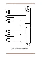
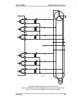
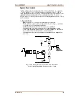
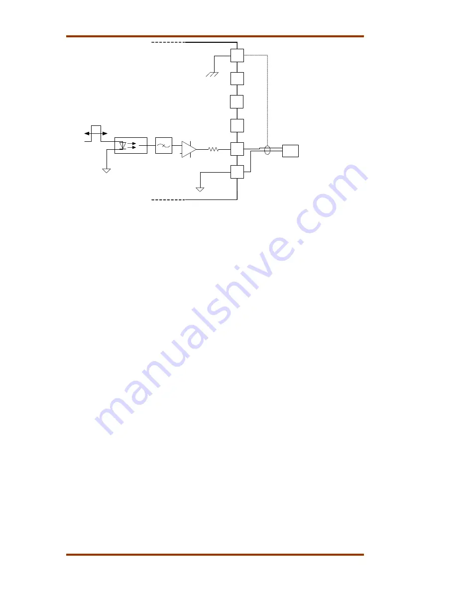
Figure 8-12. Wiring Example–Speed Bias Output Interface
(to the PowerSense Board configured for ±3 V, 0–5 V, or PWM)
Voltage Bias Output
The Voltage Bias output is configurable for 4 - 20 mA with a full scale range of 0 -
24 mA, or as a
±
1,
±
3V, or
±
9V voltage output. Configuring the output requires
wiring and application software configuration. This output is isolated from the rest
of the control system to prevent ground loops when connecting the PowerSense
board to other controls. The voltage outputs are configured in the software,
therefore the
±
9V output has about 3 times better accuracy and resolution than
the
±
3V output, which has about 3 times better accuracy and resolution than the
±
1V output.
Configuration Notes
•
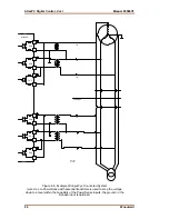
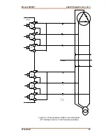
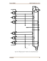
Refer to Figures 8-13 and 8-14 for Voltage Bias Output wiring.
•
The Voltage Bias output must be configured for the correct type, 4–20 mA or
the voltage type, in the application software.
•
See the specifications section for the maximum output load.
•
The output does not contain fault detection. If it is necessary to detect
failures, then the device that is driven by the analog output, for example an
actuator driver, must contain reference failure detection.
•
The output cannot be used as a voltage output and a current output, at the
same time.
Summary of Contents for AtlasPC
Page 8: ...AtlasPC Digital Control Vol I Manual 85586V1 vi Woodward...
Page 130: ...AtlasPC Digital Control Vol I Manual 85586V1 122 Woodward...
Page 131: ......
Page 132: ......
Page 133: ......

