Manual 85586V1
AtlasPC Digital Control, Vol. I
Woodward
103
RS-485 Cables
There are two options for cabling used with the RS-485 ports depending on the
length of the cable run required:
•
Standard shielded, twisted-pair for cables up to 30 m (100 ft)
•
0.3 mm² (22 AWG) low capacitance (36 pF/m or 11 pF/ft) cable for cables
up to 120 m (400 ft)
The characteristic impedance of any cable selected should be near 120
Ω
for
best performance. Refer to your cable manufacturer for more information on
characteristic impedance of cables.
The wiring must be one continuous cable between nodes, and must meet the
requirements of EIA RS-485 for 500 kbps except that Woodward recommends
that the maximum cable lengths be cut in half because typical prime mover
installations have high levels of electrical interference.
RS-422 Cables
Use 20 AWG low capacitance cable such as Belden 89207A up to 150 m (500
ft). The characteristic impedance of any cable selected should be near 120
Ω
.
Many customers are used to thinking of RS-422 and RS-485 as two-
wire networks with shield, but the transceivers used on this board
require a third “signal common” wire to ensure best performance in
noisy environments. Please be sure to allow for this when ordering
cable.
Termination
To achieve best performance with serial communication networks, it is necessary
to terminate the network to prevent interference caused by signal reflections. For
this reason, all ports on the DLE board are equipped with built-in network
termination resistors.
Customers using the pressure transducer ports (RS-422) and the driver ports
(RS-485) will be communicating with a single device, so the termination resistors
will always need to be installed on each operating port.
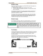
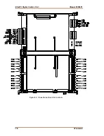
Figure 10-2. Terminator Locations
Summary of Contents for AtlasPC
Page 8: ...AtlasPC Digital Control Vol I Manual 85586V1 vi Woodward...
Page 130: ...AtlasPC Digital Control Vol I Manual 85586V1 122 Woodward...
Page 131: ......
Page 132: ......
Page 133: ......


