AtlasPC Digital Control, Vol. I
Manual 85586V1
104
Woodward
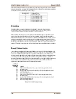
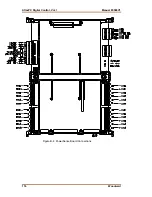
The termination resistors are connected by inserting jumper wires on the external
plug in connectors. Jumper the following pins to connect the termination resistors
as needed on the ports that you are using.
Comm Port #
Connect Pins
1
7 to 8 and 9 to 10
2
17 to 18 and 19 to 20
3
27 to 28 and 29 to 30
4
52 to 54 and 51 to 53
5
42 to 44 and 41 to 43
6
32 to 34 and 31 to 33
Shielding
Shielded cable is required between the AtlasPC and any other devices.
Unshielded cables and improperly shielded cables will very likely lead to
communication problems and unreliable control operation.
The shield must always be ac-coupled (connected through a capacitor) at one
end and connected directly to earth on the opposite end for proper operation.
The DLE board has been constructed so that the Shield/Drain connection can be
either ac-coupled or directly connected to the Atlas chassis ground which must
be tied to earth. Devices connected to the opposite end of the cable must provide
for the opposite shield connection. For instance, if the ac-coupled connection is
used on the DLE, the other end of the shield must be connected directly to earth.
Board Status Lights
The board is equipped with two LEDs labeled H and D to provide feedback from
the board. The LED labeled H indicates operation of the Honeywell portion of the
board, and LED labeled D indicates operation of the driver side of the board.
During normal operation, the LEDs will light as soon as power is applied and will
eventually turn off as the application starts running. This can take up to four
minutes, depending upon the size of the application. If the board fails its own self
test or failures are detected during normal operation, the LEDs will flash in
particular coded patterns which will repeat periodically.
LED
and
Number
of
Flashes Failure
H 1
RAM test fail (this test is done only at boot and application start)
H 2
exception error
H 3
dual port test fail (this test is done only at boot and application start)
H 4
watchdog timeout
H 7
kernel watchdog timeout
D 1
RAM test fail (this test is done only at boot and application start)
D 2
exception error
D 3
dual port test fail (this test is done only at boot and application start)
D 3
module watchdog timeout
D 7
kernel watchdog timeout
Table 10-1. DLE Failure Codes
Summary of Contents for AtlasPC
Page 8: ...AtlasPC Digital Control Vol I Manual 85586V1 vi Woodward...
Page 130: ...AtlasPC Digital Control Vol I Manual 85586V1 122 Woodward...
Page 131: ......
Page 132: ......
Page 133: ......


