AtlasPC Digital Control, Vol. I
Manual 85586V1
12
Woodward
It is expected that the installation of this equipment will include over current
protection between the power source and the AtlasPC control. This over current
protection may be accomplished by series connection of properly rated fuses or
circuit breakers. Branch circuit protection of no more than 250% of the maximum
AtlasPC power supply input current rating must be provided. See Table 2-1 for
maximum recommended fuse ratings. This value meets the 250% UL listing
requirements. The use of properly sized UL class CC, J, T, G, RK1, or RK5 fuses
meet the requirements for branch circuit protection. Do not connect more than
one AtlasPC control to any one fuse. Use only the wire size specified in Table
2-1 or equivalent metric size which meets local code requirements. Time delay
fuses should be used to prevent nuisance trips.
Table 2-1 provides the power supply holdup time specification; which is the time
the supply will continue to operate within specification after its input power is
interrupted. This information may be useful in specifying uninterruptible power
supply (UPS) systems.
Input Voltage
Range
Fuse
(Current Rating) Fuse (I
2
t Rating)
Wire Size* **
Holdup Time
18–32 Vdc**
9 A
>800
2/4 mm²
12/14 AWG
8 ms
Table 2-1. Power Supply Requirements
* 4 mm² (12 AWG) is the largest wire gauge size that may be
connected to the control power input terminal blocks.
** The minimum input voltage allowed is 18 V at the power input of
the control. The length, size of wire, and load current will determine
the minimum supply output voltage. The minimum supply voltage
measured at the source should always be greater than 18 V.
Example: two (source and return) 20 foot (6 m) lengths of 14 AWG (2
mm²) wire carrying 1.2 A (maximum rated current) will result in a
voltage drop from source output to control power input of approx.
0.16 volts. The resulting supply voltage from the example must be
greater than 18.16 volts.
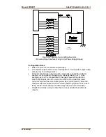
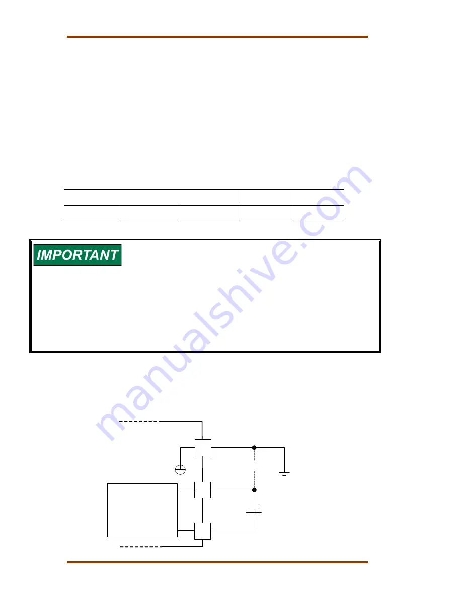
Input Power Wiring Diagram
The power supply and ground connections are located on the power supply
board.
AtlasPC
Power Supply Board
3
2
1
Common
System
Ground
24V
Optional
+
-
Switching
Power
Supply
Summary of Contents for AtlasPC
Page 8: ...AtlasPC Digital Control Vol I Manual 85586V1 vi Woodward...
Page 130: ...AtlasPC Digital Control Vol I Manual 85586V1 122 Woodward...
Page 131: ......
Page 132: ......
Page 133: ......


