Manual 85586V1
AtlasPC Digital Control, Vol. I
Woodward
29
Atlas
53
54
55
56
Active
Pickup
+V
Atlas
53
54
55
56
Active
Pickup
+V
PNP Type
NPN Type
Jumper
Jumper
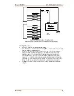
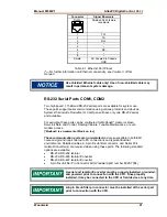
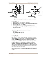
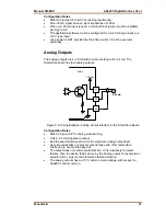
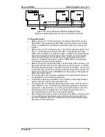
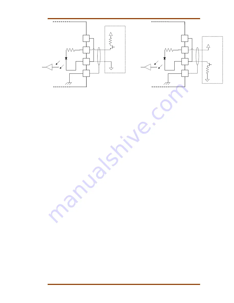
Figure 5-5. Wiring Example–Proximity Probe to the SmartCore Board
Configuration Notes
•
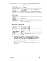
Refer to Figures 5-4 and 5-5 for speed sensor wiring.
•
Each speed input channel can only accept one MPU or one proximity probe.
•
Proximity probe power is not provided.
•
Proximity probes only—External pull-up resistors are required when
interfacing to open collector type proximity probes.
•
If the proximity probe inputs are used, the corresponding MPU inputs must
be jumpered as shown.
Speed Sensor Input Software Configuration Limitations
•
(TxMxR)/60 must be < 25,000 Hz
T = gear teeth
M = (overspeed test limit setting x 1.2)
R = gear ratio
Analog Inputs
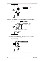
The analog inputs may be current or voltage type. If a current input is used, a
jumper is installed on the terminal block, and the software must be selected for
current. This allows the SmartCore card to use the applicable hardware
calibration values. If a voltage input is needed, the jumper must be removed, and
the software must be selected for voltage. See Figure 5-6 for jumper locations.
All analog inputs may be used with two-wire ungrounded (loop powered)
transducers or isolated (self-powered) transducers. All analog inputs have 10
Vdc of common mode rejection. If interfacing to a non-isolated device which may
have the potential of reaching over 10 Vdc with respect to the control’s common,
the use of a loop isolator is recommended to break any return current paths,
which could produce erroneous readings.
For a 4–20 mA input signal, the SmartCore board uses a 200
Ω
resistor across
the input.
Summary of Contents for AtlasPC
Page 8: ...AtlasPC Digital Control Vol I Manual 85586V1 vi Woodward...
Page 130: ...AtlasPC Digital Control Vol I Manual 85586V1 122 Woodward...
Page 131: ......
Page 132: ......
Page 133: ......


