Manual 85586V1
AtlasPC Digital Control, Vol. I
Woodward
49
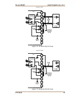
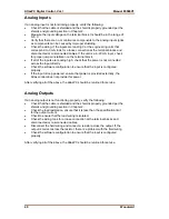
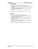
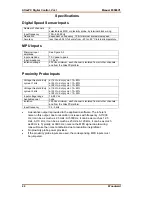
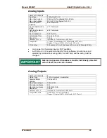
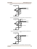
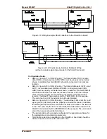
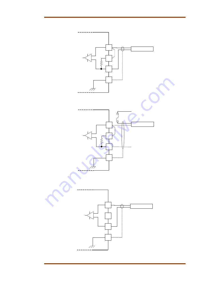
For a 4–20 mA input signal, the SmartCore board uses a 200
Ω
resistor across
the input.
Atlas
27
28
29
30
Transducer
+
4-20 mA
Self
Powered
Figure 6-5a. Wiring Example–4–20 mA Input Interface to the SmartCore Board
Atlas
27
28
29
30
Transducer
+
4-20 mA
Loop
Powered
(-) Loop Power
(+) Loop Power
100 mA Fuse
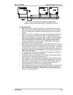
Figure 6-5b. Wiring Example–4–20 mA Input Interface using External Loop
Power
Atlas
27
28
29
30
Transducer
+
0-5 Vdc
Figure 6-6. Wiring Example–0–5 V Input Interface to the SmartCore Board
Summary of Contents for AtlasPC
Page 8: ...AtlasPC Digital Control Vol I Manual 85586V1 vi Woodward...
Page 130: ...AtlasPC Digital Control Vol I Manual 85586V1 122 Woodward...
Page 131: ......
Page 132: ......
Page 133: ......

