Manual 85586V1
AtlasPC Digital Control, Vol. I
Woodward
57
+ -
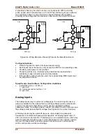
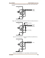
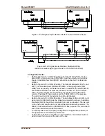
Figure 6-19. Wiring Example–RS-485 Interface to the SmartCore Board
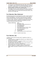
Figure 6-20. Wiring Example–Alternate Multipoint Wiring
(without a separate signal ground wire for the SmartCore board)
Configuration Notes
•
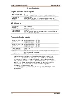
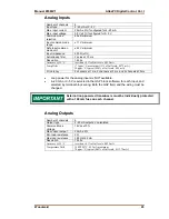
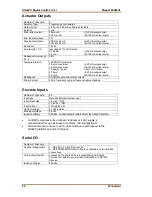
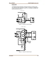
Refer to Figure 6-17 for RS-232 wiring. The transmit data (TXD), receive
data (RXD), and signal ground (SIG GND) must be properly connected as
shown. In addition the shield (SHLD) should be connected in at least one
location.
•
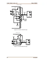
Refer to Figure 6-18 for RS-422 wiring. The transmit data pairs (422T+ and
422T-), receive data pairs (422R+ and 422R-), and signal ground (SIG
GND) must be properly connected as shown. In addition, the shield (SHLD)
should be connected in at least one location. The last unit in the network
chain, and only the last unit, should have it’s receiver terminated with a
resistor. The AtlasPC has resistors built in (TERM RES) for this purpose.
The unit at each end of the network should be terminated.
•
Refer to Figure 6-19 for RS-485 wiring. The data lines (485+ and 485–) and
signal ground (SIG GND) must be properly connected as shown. In addition,
the shield (SHLD) should be connected in at least one location. The last unit
in the chain, and only the last unit, should be terminated with a resistor. The
AtlasPC has resistors built in (TERM RES) for this purpose. The unit at each
end of the network should be terminated.
•
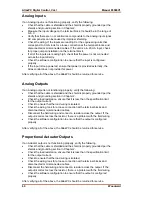
The serial ports must be properly configured in the application software for
the appropriate communication parameters.
•
Termination resistors are available on the SmartCore board and should be
wired across the network at the ends of the line.
Summary of Contents for AtlasPC
Page 8: ...AtlasPC Digital Control Vol I Manual 85586V1 vi Woodward...
Page 130: ...AtlasPC Digital Control Vol I Manual 85586V1 122 Woodward...
Page 131: ......
Page 132: ......
Page 133: ......


