AtlasPC Digital Control, Vol. I
Manual 85586V1
68
Woodward
AtlasPC Analog Combo Board Operation
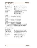
This board includes no potentiometers and requires no field calibration.
Speed Sensor Inputs
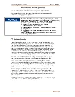
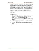
The MPU inputs are read and the speed is provided to the application program. A
derivative output is also provided. The speed sensor inputs are filtered by the
Analog Combo board, and the filter time constant is selectable at 8 milliseconds
or 16 milliseconds. Eight milliseconds should be acceptable for most turbine
applications, sixteen milliseconds may be necessary for very slow speed
applications. The speed range is selected in the application software and
determines the maximum speed that the board will detect. The control output of
the software will detect a minimum speed of one fiftieth of the speed range. This
allows detection of failed speed sensors to help prevent overspeed due to slow
update times at very low speeds. The monitor output of the GAP block will read
down to .5 Hz, irrespective of the speed range. An application may use any
combination of accepted MPUs, and any combination of speed ranges.
The Analog Combo board uses speed sensing probes mounted on a gear
connected or coupled to the turbine’s rotor to sense turbine rotor speed. Any of
the board’s speed channels accept passive magnetic pickup units (MPUs) or
proximity probes. It is not recommended that gears mounted on an auxiliary shaft
coupled to the rotor be used to sense speed. Auxiliary shafts tend to turn more
slowly than the rotor (reducing speed sensing resolution) and have coupling gear
backlash, resulting in less than optimum speed control. For safety purposes, it is
also not recommended that the speed sensing device sense speed from a gear
coupled to a generator or mechanical drive side of a system’s rotor coupling.
Atlas
57
58
59
Passive
MPU
+
GND
(isol)
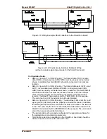
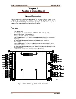
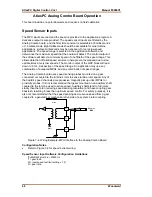
Figure 7-4. Wiring Example–MPU Interface to the Analog Combo Board
Configuration Notes
•
Refer to Figure 7-4 for speed sensor wiring.
Speed Sensor Input Software Configuration Limitations
(TxMxR)/60 must be < 25000 Hz
T = gear teeth
M = (overspeed test limit setting x 1.2)
R = gear ratio
Summary of Contents for AtlasPC
Page 8: ...AtlasPC Digital Control Vol I Manual 85586V1 vi Woodward...
Page 130: ...AtlasPC Digital Control Vol I Manual 85586V1 122 Woodward...
Page 131: ......
Page 132: ......
Page 133: ......

