Manual 85586V1
AtlasPC Digital Control, Vol. I
Woodward
71
Configuration Notes
•
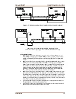
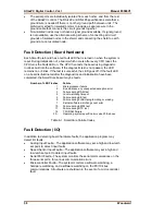
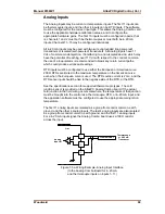
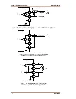
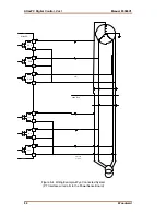
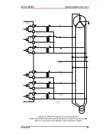
Refer to Figures 6-5, 6-6, and 6-7 for analog input wiring.
•
4–20 mA inputs are supported, 0–5 V inputs are not.
•
The application software must be configured to match the input type used,
that is, 4–20 mA, 100
Ω
RTD, k-type thermocouple, etc.
External loop powered transducers must be individually protected
with a 100 mA fuse on each channel.
RTDs
•
Only 100 and 200
Ω
RTDs are supported.
•
RTD inputs can use the European or American curve. 200
Ω
RTDs are
limited to the maximum temperature on the American curve, even when the
European curve is used.
•
The RTD source current is 2 mA.
•
The RTD sense input should be tied to the negative side of the RTD, at the
RTD.
Thermocouples
•
See the specifications section for supported thermocouple types.
•
The cold junction sensor is provided on the AtlasPC Analog Combo board. If
the actual cold junction in the field wiring occurs elsewhere, the temperature
of that junction must be brought into the control as a thermocouple, RTD, or
4–20 mA input, and the application software must be configured to use the
appropriate cold junction temperature.
•
The thermocouple and cold junction input units (°C or °F) should be
consistent in the application software.
4–20 mA Inputs
•
All 4–20 mA inputs have an impedance of 100
Ω
.
•
No loop power is provided.
External loop powered transducers must be individually protected
with a 100 mA fuse on each channel.
Summary of Contents for AtlasPC
Page 8: ...AtlasPC Digital Control Vol I Manual 85586V1 vi Woodward...
Page 130: ...AtlasPC Digital Control Vol I Manual 85586V1 122 Woodward...
Page 131: ......
Page 132: ......
Page 133: ......

