Manual 85586V1
AtlasPC Digital Control, Vol. I
Woodward
75
Chapter 8.
PowerSense Board
General Description
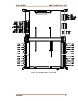
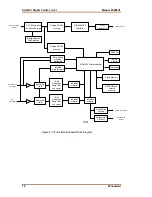
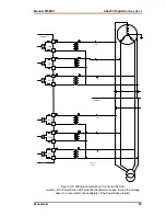
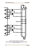
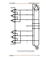
Each PowerSense board contains the circuitry for two sets of three phase ac
voltage (PT) and ac current (CT) inputs, as well as a speed bias output, a voltage
bias output, and a LON communications port.
Features
•
On-board processor for automatic calibration of the I/O channels
•
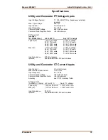
PT and CT inputs provide fundamental as well as harmonic information
•
PT and CT inputs are updated after 3 cycles, which is 50 ms at 60 Hz
•
PT and CT inputs and bias outputs have 12 bit resolution
•
PT inputs are software configurable for 70 V, 120 V, or 240 V ranges
•
Each set of PT and CT inputs is isolated from the rest of the board and chassis
•
5 ms update rate for speed and voltage bias outputs
•
Speed bias output is software configurable for 4–20 mA, 0–5 V, PWM, or ±3
V output
•
Speed Bias output is isolated from the rest of the board
•
Voltage Bias output is software configurable for 4–20 mA, ±1 V, ±3 V, and
±9 V
•
Voltage bias output is isolated from the rest of the board
•
The LON port is isolated from the rest of the board
Physical
The AtlasPC PowerSense board connects to the CPU board through the PC/104
bus. It connects to the power supply, through the AtlasPC power bus. It requires
a SmartCore board or a Pentium CPU board as a master controller. The master
controller is responsible for all application level tasks such as protective relaying,
load share, and controlling the voltage and speed bias outputs.
Hazardous Live
The following circuits are classified as Hazardous Live because they carry
potential shock hazardous voltages during normal operation or under single fault
conditions:
•
potential transformer (PT) inputs
•
current transformer (CT) inputs
•
voltage bias outputs
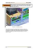
HIGH VOLTAGE—Do not contact the above inputs and outputs
during system operation when such circuits are live. Possible
serious personal injury or death could result.
HIGH VOLTAGE—Before disconnecting the secondary terminals of
the current transformer or the connections of the current transformer
at the control, ensure that the transformer is short-circuited.
Summary of Contents for AtlasPC
Page 8: ...AtlasPC Digital Control Vol I Manual 85586V1 vi Woodward...
Page 130: ...AtlasPC Digital Control Vol I Manual 85586V1 122 Woodward...
Page 131: ......
Page 132: ......
Page 133: ......


