Manual 85586V1
AtlasPC Digital Control, Vol. I
Woodward
83
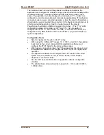
The hardware does not require three phases for voltage calculations, the
application can configure the module for single phase, and all functionality will be
modified accordingly. The single phase input that must be provided is the A
phase. The application can also configure the module for a “Y” or “delta” line
configuration, and the calculations will compensate appropriately. If the physical
connections are to a wye connected generator or load, the input to PowerSense
should also be wye connected (line-to-neutral). If the physical connections are to
a Delta connected generator or load (no neutral present), the input to
PowerSense should also be Delta connected (line-to-line). ). The “Y” or “delta”
configuration applies to the entire set of PT and CTs, it is not possible to
configure the PTs for “Y”, and the CTs for “delta”, or vice versa. However, the
configuration may differ between PT/CT 1 and PT/CT 2 (or gen and mains in a
typical configuration).
Configuration Notes
•
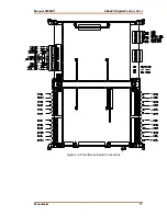
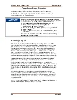
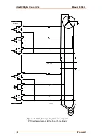
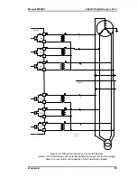
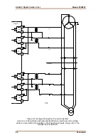
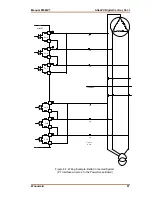
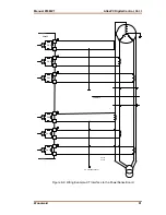
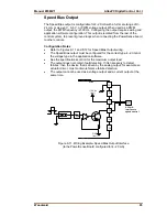
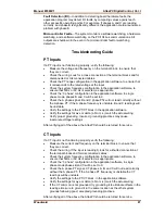
Refer to Figures 8-4 through 8-8 for PT wiring.
•
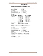
When using the 3 different PT ranges, 70 V, 120 V, and 240 V, the physical
input must be the correct voltage AND the application software must
configure the PT/CT block for the correct voltage range.
•
When using a single phase input, the PT input used must be phase A, and
the application software must configure the PT/CT block for “single phase”
operation.
•
The application software must configure the PT/CT block for the correct
system frequency 50Hz or 60 Hz, as well as for the correct rotation,
clockwise or counterclockwise.
•
See the GAP help, for information on application software configuration
variables.
•
The terminal block screws should be torqued to 8 – 10 in-lbs (0.9038782 -
1.129848 N
x
m).
Summary of Contents for AtlasPC
Page 8: ...AtlasPC Digital Control Vol I Manual 85586V1 vi Woodward...
Page 130: ...AtlasPC Digital Control Vol I Manual 85586V1 122 Woodward...
Page 131: ......
Page 132: ......
Page 133: ......

