background image

Manual 36522G 

DPG-2223-00X Controllers 


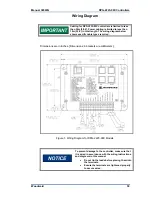
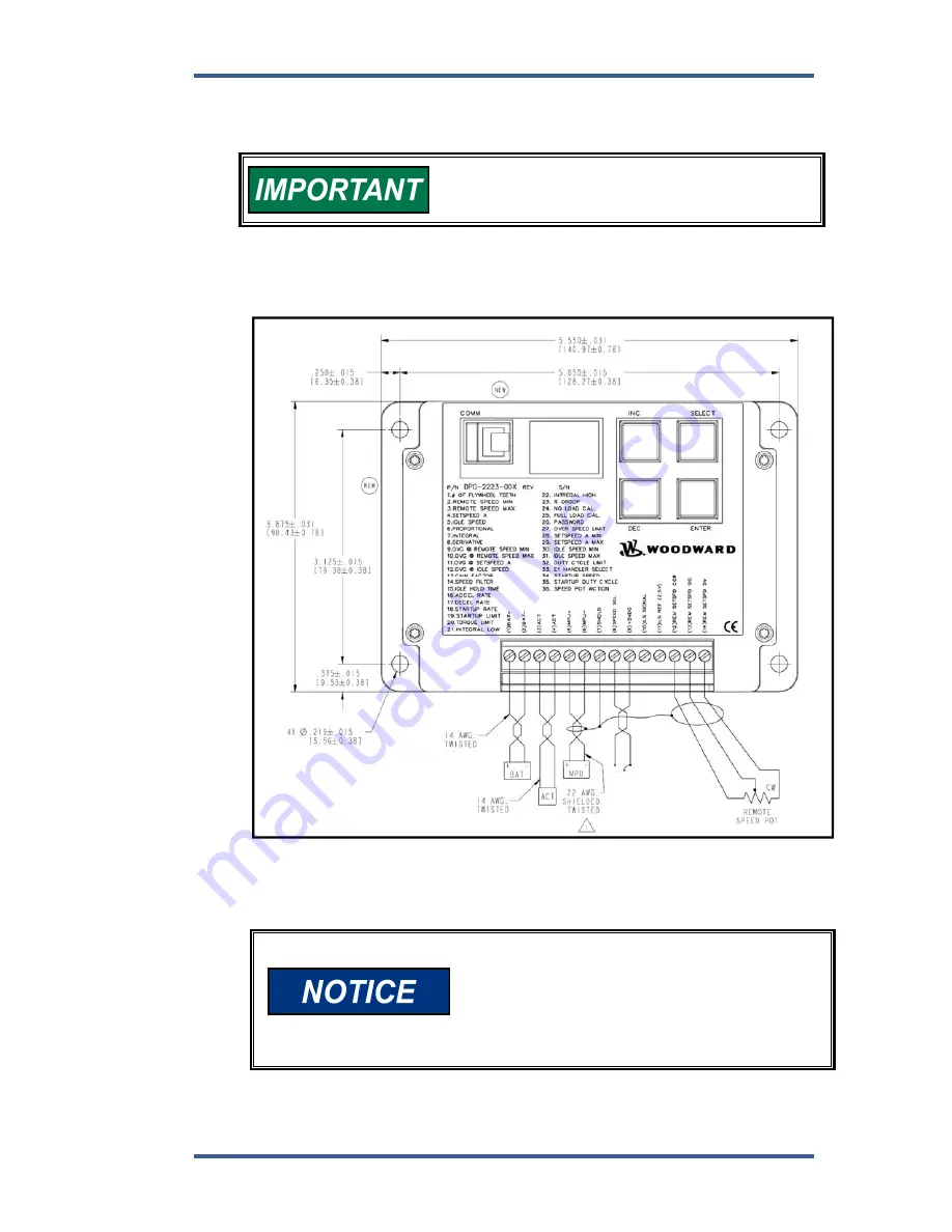
Wiring Diagram 


Cabling for DPG 2233-00X controllers is limited to less 
than 30m (98.4’). Power cabling is limited to less than 
10m (32.8’) in total length. The wiring diagram below 
shows specific cable types required. 


Dimensions are in inches. [Dimensions in brackets are millimeters.] 


Woodward 

39 


R E M O T E /  

S E T   S P E E D   A  

S E L E C T  

Figure 1. Wiring Diagram for DPG-2223-00X Models 


To prevent damage to the controller, make sure that 
it is wired in accordance with the wiring instructions 
and diagrams in this manual. 


Do not tin the leads before placing them into 
the terminals. 


Ensure the terminals are tightened properly 
to secure wires. 


Summary of Contents for DPG-2223-00 Series

Page 1: ...chnical Manual 36522 Revision G Original Instructions DPG 2223 00X Digital Controllers Programmable Controllers for Isochronous Generators with Load Sharing Capability Installation and Operation Manua...

Page 2: ...that you have the latest revision be sure to check the Woodward website www woodward com pubs current pdf The revision level is shown at the bottom of the front cover after the publication number The...

Page 3: ...ed A required 13 3 12 OVG Idle Speed optional 13 3 13 Gain Factor required 14 3 14 Speed Filter required 14 3 15 Idle Hold Time optional 14 3 16 Accel Rate optional 15 3 17 Decel Rate optional 15 3 18...

Page 4: ...nce 37 CHAPTER 6 INSTALLATION INSTRUCTIONS 38 Terminal Descriptions 38 Wiring Diagram 39 Centralized Suppression 40 CHAPTER 7 DIAGNOSTICS TROUBLESHOOTING 42 Display Codes 42 Troubleshooting Table 43 C...

Page 5: ...Manual 36522G DPG 2223 00X Controllers Regulatory Compliance Declaration of Conformity Woodward iii...

Page 6: ...be implemented to help protect the control and other components on the bus See Chapter 6 Installation Instructions COMM Port The COMM port is intended to be a service port with only temporary connect...

Page 7: ...h as plastic or Styrofoam cups cup holders cigarette packages cellophane wrappers vinyl books or folders plastic bottles and plastic ash trays away from the control the modules and the work area as mu...

Page 8: ......

Page 9: ...orque limits idle speed set and idle hold time The controller can also provide droop speed control with 100 user selectable droop levels The controller s internal FAILSAFE reacts instantly to loss of...

Page 10: ...gth See wiring diagrams for specific cable types required Mechanical Ambient Operating Temperature 40 F to 185 F 40 C to 85 C Sealing Oil water and dust resistant via conformal coating and die cast en...

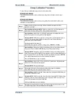
Page 11: ...perates in two modes PARAMETER SELECT MODE and PARAMETER EDIT MODE For each of these modes the keypad and the display have a unique way of operating The following tables provide a quick reference to t...

Page 12: ...ssword parameter in the Parameter Reference chapter for more information about using password protection Right digit s decimal point is blinking or ON The lower two digits the tens digit and the ones...

Page 13: ...yed For example If the controller s label lists 36 parameters then pressing the INC key when the display is blinking the value 36 will cause the display to wrap around to the first parameter listed an...

Page 14: ...values and indicate the operating mode of the user interface When the value being displayed by the two 7 segment LEDs is blinking PARAMETER SELECT MODE is active When the value displayed is not blink...

Page 15: ...re editing is currently 1800 then after pressing the DEC key the parameter s new value will be 1799 DECIMAL TO HEXADECIMAL CONVERSION CHART Decimal Value Hexadecimal Equivalent 10 A 11 B 12 C 13 D 14...

Page 16: ...f the parameters have minimum and maximum values set by other parameters Parameters listed in boldface are required settings for the controller Note also that all Speed and Rate values are shown as ma...

Page 17: ...e 1000 1 11000 17 Decel Rate 1000 1 11000 18 Startup Rate 1000 1 11000 19 Startup Limit 1000 0 1000 20 Torque Limit 1000 0 1000 21 Integral Low Limit 0 0 Integral High Limit 22 Integral High Limit 99...

Page 18: ...to a value other than zero enables Hz to RPM conversion Adjust this parameter to a value equal to the exact number of pulses that the MPU delivers to the controller in one revolution of the engine to...

Page 19: ...ustable range for REMOTE SPEED MAX extends from REMOTE SPEED MIN to 11 000 hertz When REMOTE SPEED MAX values greater than 9999 are displayed the left most digit uses the capital letter A to represent...

Page 20: ...value produces a unique controller output value Saturation Saturation Proportional response a higher Proportional value Increases output response to a step change in error a lower Proportional value D...

Page 21: ...f the remote speed pot When OVG Remote Speed Max is a non zero value dual point sloped gain is used and a new gain value is computed based on the current speed 3 10 OVG Remote Speed Max optional This...

Page 22: ...here are This is because the number of acceleration deceleration cycles increases and these oscillations will have lower amplitude With more cylinders there is less time for the speed to slow down bef...

Page 23: ...s specified in MPU magnetic pickup Hertz per second based on the following formula higher_speed_in_Hertz lower_speed_in_Hertz ramp_time_in_seconds decel_rate_value For example suppose Set Speed A is 4...

Page 24: ...and STARTUP RATE parameters are displayed as a RPM quantity per second instead of Hz sec values The given rate formulas can be used to compute rates in terms of RPM values by substituting the Hertz s...

Page 25: ...uence on lowering PID output must stop The default value is 0 The value can be adjusted from 0 to 90 in 1 increments Use carefully as improper use can prevent the controller from ever reaching the tar...

Page 26: ...bration Instructions chapter for more information Droop mode relies on knowing the actuator position The actuator s position corresponds to the amount of fuel being delivered to the engine The DPG 222...

Page 27: ...an be modified with built in user interface only not Universal PST DISABLED This setting turns off any password protection Use this setting if password protection is not desired This is the default se...

Page 28: ...ine can be restarted 3 28 Set Speed A Min optional Set Speed A Min is used to set the lowest value allowed for adjustments of Set Speed A This parameter can be set to any value within the range border...

Page 29: ...he E1 Handler Select parameter value is one the E1 error is automatically cleared when the Remote Set Speed Signal returns to 0 2 0 35V Speed Pot Action 0 or 4 65 4 8V Speed Pot Action 1 When the E1 H...

Page 30: ...y cycle value close to that needed for the actuator to allow enough fuel to idle e engine th If the value is too low then the engine crank time may be longer than desired because the controller s actu...

Page 31: ...put increases the engine speed increases When in reverse acting mode as the voltage at the Remote Set Speed Signal input decreases the engine speed increases This is shown in the table below PEDAL ACT...

Page 32: ...ming Features Universal PST features include Automatic configuration to each DPG when communications are established Read write access to all DPG programmable parameters and features View each paramet...

Page 33: ...Contact the Woodward sales department to request a DPG Software Calibration Kit for a nominal charge Downloading Universal PST The Universal PST application can be downloaded from the Woodward Softwa...

Page 34: ...r s power and operating system Do not interrupt the installation program even though it may appear as though it is not running NOTE Administrator rights may be needed to install on some Microsoft Wind...

Page 35: ...ersal PST User Interface Overview Universal PST has two main display modes Table View the main startup screen Chart View TABLE VIEW In Table View the user can View the current values for all user prog...

Page 36: ...main parameter setup table Press the Data File button to open a file for saving chart recorder data Press the Data Reset button to start data collection to the open file at the beginning Press the Pau...

Page 37: ...ently in communication with the PC Information about the Universal PST for DPG application Parameter Setup The Parameter Setup panel displays a table where each row shows the Name of a user programmab...

Page 38: ...ORTANT If the communication cable is unplugged from a DPG and plugged into a different DPG while the Universal PST application is still running then the Read All button must be pressed in order for Un...

Page 39: ...The Vertical Scale options provide three different ways to view engine speed data The 0 to 12000 Hz option is the default and sets the vertical axis range to its absolute minimum and maximum measurab...

Page 40: ...suffixes The first 60 000 data points are saved in filename00 csv and the next 60 000 data point are saved in filename01 csv and so on until a million data points are collected This is to prevent each...

Page 41: ...INTEGRAL 50 8 DERIVATIVE 25 11 OVG SET SPEED A 20 13 GAIN FACTOR note 1 20 14 SPEED FILTER note 2 16 34 STARTUP SPEED 1000 NOTE 1 Modify Gain Factor only if you run out of adjustment in a PID or OVG...

Page 42: ...l a speed error may persist after a load on load off transition Therefore during steps 3 5 you should temporarily increase the integral to get the engine speed back to the set speed and then reset the...

Page 43: ...P 1000 Step 4 User Interface Allow the engine to stabilize at the no load droop speed then press the controller s ENTER key to set the percent droop Universal PST Allow the engine to stabilize at the...

Page 44: ...andler Select 2 The calibration sequence can be done using either the controller s built in user interface or Universal PST Step 1 Connect a potentiometer to the governor Refer to wiring diagram in Ch...

Page 45: ...his example the STARTUP SPEED is set to 500 Hertz the STARTUP RATE is set equal to 250 Hertz per second and the IDLE SPEED is set to 1500 Hertz It will take 4 seconds for the target speed to ramp up 1...

Page 46: ...Speed Pot COM Common for the remote speed pot CCW 13 Remote Speed Pot SIG Remote Speed Signal Input Voltage Range E1 Handler Mode 0 0 20 to 4 80 Vdc E1 Handler Mode 1 0 20 to 4 80 Vdc E1 Handler Mode...

Page 47: ...ypes required Dimensions are in inches Dimensions in brackets are millimeters Woodward 39 R E M O T E S E T S P E E D A S E L E C T Figure 1 Wiring Diagram for DPG 2223 00X Models To prevent damage to...

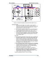
Page 48: ...tched ON and OFF wired on the same power bus 3 Large surge pulses are typically due to indirect lightning strikes Some surge pulses may also be present due to series inductances with switched currents...

Page 49: ...m Woodward as 8923 1272 KIT This kit is for a 24V system It will suppress alternator load dump from alternators within the 200A range as well as indirect lightning pulses that may be coupled to the po...

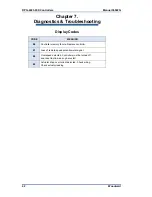
Page 50: ...ng Display Codes CODE MEANING E0 Controller memory failure Replace controller E1 Loss of remote speed potentiometer signal E2 Overspeed detected Controller must be turned off and reset to allow an eng...

Page 51: ...U gap Try reversing the MPU leads If a speed signal is present measure actuator output duty cycle If not greater than 5 then restore all parameter values to factory default settings and crank the engi...

Page 52: ...Improve PID tuning Speed filter setting is too low Fuel is restricted Check actuator linkage Battery voltage is too low Engine Instability With Load Improve PID tuning Fuel is restricted Check actuat...

Page 53: ...ystem documentation for details Woodward Business Partner Support Woodward works with and supports a global network of independent business partners whose mission is to serve the users of Woodward con...

Page 54: ...e Distributor Charges for the Replacement Exchange service are based on a flat rate plus shipping expenses You are invoiced the flat rate replacement exchange charge plus a core charge at the time the...

Page 55: ...roduct Training Field Service Technical Support is available from your equipment system supplier your local Full Service Distributor or from many of Woodward s worldwide locations depending upon the p...

Page 56: ...636 7080 Poland 48 12 295 13 00 The Netherlands 31 23 5661111 United States 1 970 482 5811 You can also contact the Woodward Customer Service Department or consult our worldwide directory www woodward...

Page 57: ...Manual 36522G DPG 2223 00X Controllers Woodward 49...

Page 58: ...ast Drake Road Fort Collins CO 80525 USA Phone 1 970 482 5811 Fax 1 970 498 3058 Email and Website www woodward com Woodward has company owned plants subsidiaries and branches as well as authorized di...

Reviews: