Manual 37138C
ESDR 4T - Current Differential Protection Relay
Page 18/46
© Woodward
Electrical Restraint of Inrush Current and Overexcitation with Transformers
Certain transformer operational conditions can cause differential currents without there actually being a fault pre-
sent at the protected object. This includes energizing the transformer and operating in overexcitation mode.
When a transformer is energized, a current inrush flows in on one side which can be variably high depending on
the instantaneous value of the supply current. If a long high-voltage line has a transformer at the end that is being
energized, overvoltages can occur and overexcite the transformer, inducing increased currents on one side. As
the currents only flow one-sided in both cases, a differential current will be measured which results in false trip-
ping.
During an inrush current there are typically high proportions of 2nd order harmonics present. However during
overexcitation there are predominantly 5th order harmonics present. The harmonics component is determined in
the ESDR 4T using the digital Fourier transformation (= DFT) and this is used as the criteria for electrical re-
straint against false tripping.
To activate the electrical restraint of an inrush current or an overexcitation, enable the "Stabilization Rush" func-
tion in the configuration mode by configuring as ON and set an operate margin in the next screen. The operate
margin must be set for rush detection. This limit must be set so that it is not exceeded in normal operation. But it
must be exceeded if an inrush current occurs. The proportion of 2
nd
harmonics in normal operation and in the
starting current depends in part on the type of transformer construction and the starting torque. As such, no gen-
eral operate margin can be given here. The documentation contains notes stating that the proportion of 2
nd
order
harmonics when there is inrush current is always over 50 % and always under 30 % when there is a short-circuit.
Only step 1 of the differential current tripping can be stabilized; step 2 causes constant tripping. When electrical
restraint is activated you should ensure that the time lag for monitoring the differential current 1 is at least
0.08 seconds.
Self-Monitoring
≡≡≡≡≡≡≡≡≡≡≡≡≡≡≡≡≡≡≡≡≡≡≡≡≡
The unit is equipped with an operational readiness message for self-monitoring. It is available externally via a
contact assembly. The ready for operation signal is disabled if the unit's supply voltage drops below approxi-
mately 19 Vdc or if there is an internal malfunction.
Configuration
≡≡≡≡≡≡≡≡≡≡≡≡≡≡≡≡≡≡≡≡≡≡≡≡≡
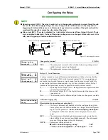
The operating parameters may be entered in through the buttons on the front panel. To change these parameters,
the control must be in the configuration mode. The control unit will continue to operate while in the configura-
tion mode. This may result in the control unit accidentally issuing a breaker open command if the parameters are
changed while in the operation mode.


