Programmable Logic
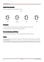
Available Gates (Operators)
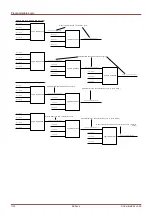
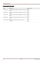
Within the Logic Equation, the following Gates can be used:
Input Signals
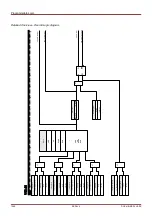
The user can assign up to 4 Input signals (from the assignment list) to the inputs of the gate.
As an option, each of the 4 input signals can be inverted (negated)
Timer Gate (On Delay and Off Delay)
The output of the gate can be delayed. The user has the option to set an On and an Off delay.
Latching
The logic equations issues two signals. An unlatched and a latched signal. The latched output is also available as
an inverted output.
In order to reset the latched signal the user has to assign a reset signal from the assignment list. The reset signal
can also optionally be inverted. The latching works based on reset priority. That means, the reset input is dominant.
1100
MCDLV4
DOK-HB-MCDLV4-2E
&
AND
NAND
OR
NOR
Gate
&
>1
>1
Summary of Contents for HighPROtec MCDLV4
Page 3: ...Order Code Order Code 3 MCDLV4 DOK HB MCDLV4 2E...
Page 47: ...Installation and Connection 47 MCDLV4 DOK HB MCDLV4 2E...
Page 164: ...Input Output and LED Settings 164 MCDLV4 DOK HB MCDLV4 2E...
Page 433: ...Parameters 433 MCDLV4 DOK HB MCDLV4 2E...
Page 457: ...Device Parameters 457 MCDLV4 DOK HB MCDLV4 2E...
Page 473: ...Blockings 473 MCDLV4 DOK HB MCDLV4 2E...
Page 988: ...Protective Elements 988 MCDLV4 DOK HB MCDLV4 2E P P Q P Q P Q Q Q P S S...
Page 989: ...Protective Elements 989 MCDLV4 DOK HB MCDLV4 2E Pr Q P Q P Qr...
Page 1023: ...Protective Elements 1023 MCDLV4 DOK HB MCDLV4 2E...

