Communication Protocols
IEC60870-5-103
IEC 103
IEC60870-5-103 Protocol Configuration
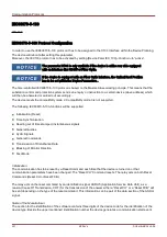
In order to use the IEC60870-5-103 protocol it has to be assigned to the X103 Interface within the Device Planning.
The device will reboot after setting this parameter.
Moreover, the IEC103 protocol has to be activated by setting [Device Para/ IEC 103]
»Function« to “active”.
The parameter X103 is only available if the device is at the rear side equipped
with an interface like RS485 or Fiber Optic.
If the device is equipped with an Fiber Optic Interface, the Optical Rest Position
has to be set within the Device Parameters .
The time-controlled IEC60870-5-103 protocol is based on the Master-Slave working principle. This means that the
substation control and protection system sends an enquiry or instruction to a certain device (slave address) which
will then be answered or carried out accordingly.
The device meets the compatibility mode 2. Compatibility mode 3 is not supported.
The following IEC60870-5-103-functions will be supported:
Initialization (Reset)
Time Synchronization
Reading out of time stamped, instantaneous signals
General Queries
Cyclic Signals
General Commands
Transmission of Disturbance Data
Blocking of Monitor Direction
Test Mode
Initialization
The communication has to be reset by a Reset Command each time that the device is turned on or that
communication parameters have been changed. The “Reset CU” Command resets. The relay acts on both Reset
Commands (Reset CU or Reset FCB).
The relay acts on the reset command by an identification signal ASDU 5 (Application Service Data Unit), as a
reason (Cause Of Transmission, COT) for the transmission of the answer either a “Reset CU” or a “Reset FCB” will
be sent depending on the type of the reset command. This information can be part of the data section of the ASDU-
signal.
Name of the Manufacturer
The section for the identification of the software contains three digits of the device code for the identification of the
device type. Beside the upper mentioned identification number the device generates a communication start event.
321
MCDLV4
DOK-HB-MCDLV4-2E
Summary of Contents for HighPROtec MCDLV4
Page 3: ...Order Code Order Code 3 MCDLV4 DOK HB MCDLV4 2E...
Page 47: ...Installation and Connection 47 MCDLV4 DOK HB MCDLV4 2E...
Page 164: ...Input Output and LED Settings 164 MCDLV4 DOK HB MCDLV4 2E...
Page 433: ...Parameters 433 MCDLV4 DOK HB MCDLV4 2E...
Page 457: ...Device Parameters 457 MCDLV4 DOK HB MCDLV4 2E...
Page 473: ...Blockings 473 MCDLV4 DOK HB MCDLV4 2E...
Page 988: ...Protective Elements 988 MCDLV4 DOK HB MCDLV4 2E P P Q P Q P Q Q Q P S S...
Page 989: ...Protective Elements 989 MCDLV4 DOK HB MCDLV4 2E Pr Q P Q P Qr...
Page 1023: ...Protective Elements 1023 MCDLV4 DOK HB MCDLV4 2E...


