Switchgear/Breaker – Manager
Single Line Diagram
The user can create and modify Single Lines (pages) by means of the
Page Editor.
The Single Lines (Control Pages) have to be loaded into the protective device by means of
Smart view.
For details on the creation, modification and upload of Single Lines (Control Pages) please refer to the manual
“page_editor_uk.pdf” or contact the technical support. The manual can be accessed via the
Page Editors help
menu.
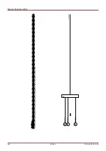
The single line diagram includes the graphically description of the switchgear and its designation (name) as well as
its features (short circuit proof or not ...). For displaying in the devices software, the switchgears' designations (e. g.
QA1, QA2, instead of SG[x]) will be taken from the single line diagram (configuration file).
The configuration file includes the single line diagram and the switchgear properties. Switchgear properties and
single line diagram are coupled via the configuration file.
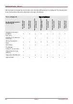
The default settings of the switchgears depend on the used Single Line. The shown
default values correspond to a Single Line with two circuit breakers and to isolating
switches.
498
MCDLV4
DOK-HB-MCDLV4-2E
Summary of Contents for HighPROtec MCDLV4
Page 3: ...Order Code Order Code 3 MCDLV4 DOK HB MCDLV4 2E...
Page 47: ...Installation and Connection 47 MCDLV4 DOK HB MCDLV4 2E...
Page 164: ...Input Output and LED Settings 164 MCDLV4 DOK HB MCDLV4 2E...
Page 433: ...Parameters 433 MCDLV4 DOK HB MCDLV4 2E...
Page 457: ...Device Parameters 457 MCDLV4 DOK HB MCDLV4 2E...
Page 473: ...Blockings 473 MCDLV4 DOK HB MCDLV4 2E...
Page 988: ...Protective Elements 988 MCDLV4 DOK HB MCDLV4 2E P P Q P Q P Q Q Q P S S...
Page 989: ...Protective Elements 989 MCDLV4 DOK HB MCDLV4 2E Pr Q P Q P Qr...
Page 1023: ...Protective Elements 1023 MCDLV4 DOK HB MCDLV4 2E...

