Switchgear/Breaker – Manager
Switchgear Configuration
Wiring
At first the switchgear positioning indicators have to be connected to the digital inputs of the protection device.
One of the position indicators (either the »Aux ON
« or the »Aux OFF«) contact has to be connected necessarily. It
is recommended also to connect the »Aux OFF
« contact.
Thereafter the command outputs (relay outputs) have to be connected with the switchgear.
Please observe the following option: In the general settings of a circuit breaker, the
ON/OFF commands of a protection element can be issued to the same output relays,
where the other control commands are issued.
If the commands are issued to different relays output relays the amount of wiring
increases.
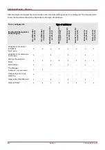
Assignment of Position Indications
The position indication is needed by the device to get (evaluate) the information about the current status /position of
the breaker. The switchgear position indications are shown in the devices display. Each position change of a
switchgear results in a change of the corresponding switchgear symbol.
For the detection of a switchgear's position always two separate Aux contacts are
recommended! If only one Aux contact is used, no intermediate or disturbed positions
can be detected.
A (reduced) transition supervision (time between issue of the command and position
feedback indication of the switchgear) is also possible by one Aux contact.
In the menu [Control/SG/SG [x] ] the assignments for the position indications have to be set.
Detection of switchgear position with two Aux contacts – Aux ON and Aux OFF (recommended!)
For detection of their positions switchgear are provided with Aux contacts (Aux ON and Aux OFF). It is
recommended to use both contacts to detect intermediate and disturbed positions too.
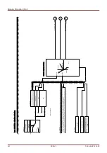
The protection device continuously supervises the status of the inputs
»Aux ON-I« and »Aux OFF-I«.
These signals are validated based on the supervision timers »
t-Move ON« and »t-Move OFF« validation functions.
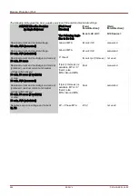
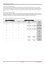
As a result, the switchgear position will be detected by the following signals (examples):
Pos ON
Pos OFF
Pos Indeterm
Pos Disturb.
Pos (State=0, 1, 2 or 3)
502
MCDLV4
DOK-HB-MCDLV4-2E
Summary of Contents for HighPROtec MCDLV4
Page 3: ...Order Code Order Code 3 MCDLV4 DOK HB MCDLV4 2E...
Page 47: ...Installation and Connection 47 MCDLV4 DOK HB MCDLV4 2E...
Page 164: ...Input Output and LED Settings 164 MCDLV4 DOK HB MCDLV4 2E...
Page 433: ...Parameters 433 MCDLV4 DOK HB MCDLV4 2E...
Page 457: ...Device Parameters 457 MCDLV4 DOK HB MCDLV4 2E...
Page 473: ...Blockings 473 MCDLV4 DOK HB MCDLV4 2E...
Page 988: ...Protective Elements 988 MCDLV4 DOK HB MCDLV4 2E P P Q P Q P Q Q Q P S S...
Page 989: ...Protective Elements 989 MCDLV4 DOK HB MCDLV4 2E Pr Q P Q P Qr...
Page 1023: ...Protective Elements 1023 MCDLV4 DOK HB MCDLV4 2E...

