Protective Elements
Backup Protection
In principle, there are two strategies for a backup protection:
1. The backup protection functions are active all the time, i. e. In parallel with the line differential protection.
2. The backup protection functions get enabled as soon as the quality of the Protection Communication is no
longer sufficient. (This means that the backup functions are blocked as long as the line differential
protection operates normally.)
For „strategy No. 1“, the user has to configure the required backup functions (typically overcurrent protection, e. g.
ANSI 50, 51, 51Q, 51V, 67) as usual, i. e. independent of the line differential protection. This is described in the
respective chapters of this manual. In other words, there are no settings or activities specific to differential
protection involved.
For every protection function, there are always two independent blocking inputs available. Therefore „strategy
No. 2“ can be accomplished by assigning the output signal
Comm. Ok (see Chapter “ProtCom – Protection
Communication”) to a blocking input of the required backup protection. Whenever the quality of the Protection
Communication is not sufficient anymore the
Comm. Ok signal gets automatically reset so that the blocking of the
backup protection gets released.
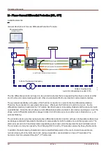
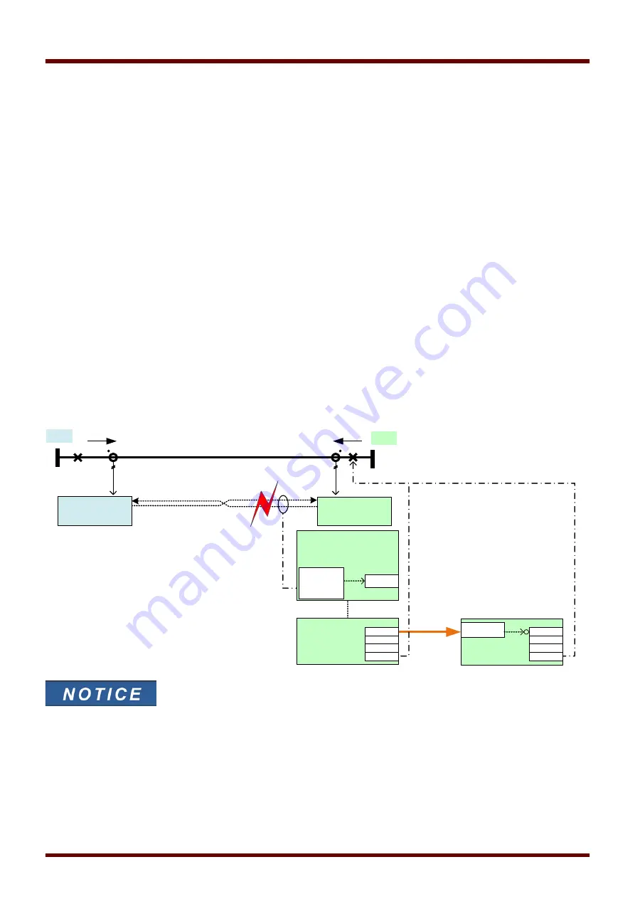
The following diagram may be seen as an example for strategy 2: If the “ProtCom” module, which is fundamental
for the differential protection, detects transmission problems the “Id” phase differential protection module gets
blocked automatically.
During a restart of the protective device the “ProtCom” communication
becomes active some seconds later than the protection becomes active,
therefore the backup overcurrent protection module is active during this time.
603
MCDLV4
DOK-HB-MCDLV4-2E
Id
_Z
0
6
A
B
internal
Assignment
Emergency
Protection (Backup
Overcurrent)
monitor: Tx, Rx
Fiber defective
IB
prim
IA
prim
CT
A
CT
B
Device
A
Device
B
ProtCom
Comm. Ok
active
Id
I[6]
ExBlo 1
active
Alarm
Trip
TripCmd
active
Alarm
Trip
TripCmd
active
Alarm
Trip
TripCmd
Summary of Contents for HighPROtec MCDLV4
Page 3: ...Order Code Order Code 3 MCDLV4 DOK HB MCDLV4 2E...
Page 47: ...Installation and Connection 47 MCDLV4 DOK HB MCDLV4 2E...
Page 164: ...Input Output and LED Settings 164 MCDLV4 DOK HB MCDLV4 2E...
Page 433: ...Parameters 433 MCDLV4 DOK HB MCDLV4 2E...
Page 457: ...Device Parameters 457 MCDLV4 DOK HB MCDLV4 2E...
Page 473: ...Blockings 473 MCDLV4 DOK HB MCDLV4 2E...
Page 988: ...Protective Elements 988 MCDLV4 DOK HB MCDLV4 2E P P Q P Q P Q Q Q P S S...
Page 989: ...Protective Elements 989 MCDLV4 DOK HB MCDLV4 2E Pr Q P Q P Qr...
Page 1023: ...Protective Elements 1023 MCDLV4 DOK HB MCDLV4 2E...

