Protective Elements
Phasor Compensation
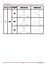
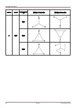
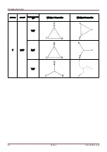
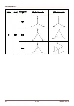
Please note: This section applies only if a step up transformer is part of the protected differential zone.
Please note: The reference side for the phasor compensation is assigned fixed to current measuring card W1.
The phase current phasor compensations are performed automatically and involve amplitude and phase
adjustments based on the system parameters, voltage ratings, tap position (assuming the tap changer is on the
winding 1 side), winding connections and groundings, and the secondary winding phase shift (n) relative to the
primary.
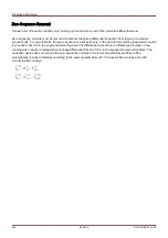
The compensated secondary current phasor on the transformer winding side W2 with winding side W1 as reference
winding can be expressed as follows:
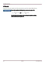
⃗
I
W2
'
=
V
LL,W2
V
LL,W1
⋅
(
1
+
Tap Changer
)
⋅
CT
pri , W2
CT
pri , W1
⋅
⃗
I
W2
for magnitude compensation,
and
⃗
I
W2
' '
=
T
Phase Shift
(
n
)
⋅
⃗
I
W2
'
for angle compensation.
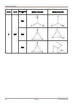
Note:
T
Phase Shift
n
is a complex factor due to transformer vector group setting.
607
MCDLV4
DOK-HB-MCDLV4-2E
Summary of Contents for HighPROtec MCDLV4
Page 3: ...Order Code Order Code 3 MCDLV4 DOK HB MCDLV4 2E...
Page 47: ...Installation and Connection 47 MCDLV4 DOK HB MCDLV4 2E...
Page 164: ...Input Output and LED Settings 164 MCDLV4 DOK HB MCDLV4 2E...
Page 433: ...Parameters 433 MCDLV4 DOK HB MCDLV4 2E...
Page 457: ...Device Parameters 457 MCDLV4 DOK HB MCDLV4 2E...
Page 473: ...Blockings 473 MCDLV4 DOK HB MCDLV4 2E...
Page 988: ...Protective Elements 988 MCDLV4 DOK HB MCDLV4 2E P P Q P Q P Q Q Q P S S...
Page 989: ...Protective Elements 989 MCDLV4 DOK HB MCDLV4 2E Pr Q P Q P Qr...
Page 1023: ...Protective Elements 1023 MCDLV4 DOK HB MCDLV4 2E...

