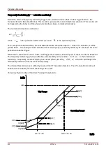
Protective Elements
Retrofitting – External Compensation
Please note: This section applies only if a step up transformer is part of the protected differential zone.
By using the external removal approach, just like many elctromechnical relays do, the
relay will not see the zero sequence current (unlike other protection functions, such as
residual overcurrent, ground differential , etc.)
For a retrofit project, if the user has CTs externally connected in such a way that the zero sequence currents are
removed automatically, then the internal zero sequence currents compensation will not be needed. However, if the
user prefers the external approach of zero sequence current removal, the user must be aware that the protective
device is a multi-function, digital protection system and the phase differential function is one of them. By using the
external removal approach, the relay will not see the zero sequence current on which other functions such as
residual overcurrent functions, ground differential function, etc. are just based on. If the user is only interested in
the phase differential function in this relay, attention must be paid to the phase shift and CT ratios. Under normal or
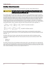
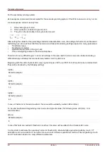
external fault conditions, the CT secondary currents from two windings should be equal in magnitude, i. e.:
∣
CT
Sec , W1
CT
Pri , W1
/
√
3
⋅
⃗
I
Pri ,W1
∣
=
∣
CT
Sec ,W2
CT
Pri , W2
⋅
⃗
I
Pri ,W2
∣
if the W1 CTs are delta-connected; or
∣
CT
sec , W1
CT
pri , W1
⋅
⃗
I
Pri ,W1
∣
=
∣
CT
sec , W2
CT
pri ,W2
/
√
3
⋅
⃗
I
Pri ,W2
∣
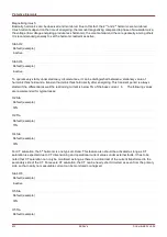
if the W2 CTs are delta-connected.
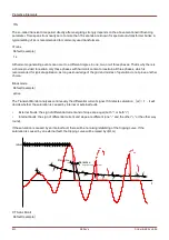
The user must provide the relay with the modified CT primary rating to accommodate the current's effective
decrease due to the CT delta connection. The CT primary rating setting on the CT delta connected side should be
divided by
3
.
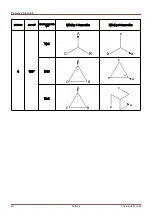
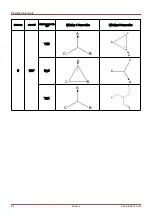
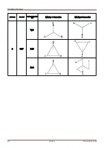
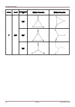
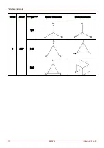
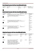
The phase shift n for the CT delta connected case should include the phase shift from transformer winding
connections and additional phase shift from CT delta connection. There are only two methods for the CT delta
connection:
•
DAB (dy1) or
•
DAC (dy11)
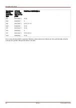
For instance, if the user has a Yd1 transformer and the neutral on the Y side is grounded, the user must have CTs
on the Y side connected as DAC (Dy11), then the user has total phase shift 1+11=12 (same as 0 in terms of phase
shift). If the user has a Yd5 transformer and the neutral on the Y side is grounded, the user must have CTs on the Y
side connected as DAB (Dy1), then the user has total phase shift 5+1=6.
623
MCDLV4
DOK-HB-MCDLV4-2E
Summary of Contents for HighPROtec MCDLV4
Page 3: ...Order Code Order Code 3 MCDLV4 DOK HB MCDLV4 2E...
Page 47: ...Installation and Connection 47 MCDLV4 DOK HB MCDLV4 2E...
Page 164: ...Input Output and LED Settings 164 MCDLV4 DOK HB MCDLV4 2E...
Page 433: ...Parameters 433 MCDLV4 DOK HB MCDLV4 2E...
Page 457: ...Device Parameters 457 MCDLV4 DOK HB MCDLV4 2E...
Page 473: ...Blockings 473 MCDLV4 DOK HB MCDLV4 2E...
Page 988: ...Protective Elements 988 MCDLV4 DOK HB MCDLV4 2E P P Q P Q P Q Q Q P S S...
Page 989: ...Protective Elements 989 MCDLV4 DOK HB MCDLV4 2E Pr Q P Q P Qr...
Page 1023: ...Protective Elements 1023 MCDLV4 DOK HB MCDLV4 2E...


