Protective Elements
Measuring Mode
For all protection elements it can be determined, whether the measurement is done on basis of the »
Fundamental«
or if »
TrueRMS« measurement is used.
Alternatively the »
Measuring Mode« can be set to »I2«. In this case the negative phase sequence current will be
measured. This is to detect unbalanced faults.
Voltage restraint overcurrent protection 51V
When the Parameter »
VRestraint« is set to active the overcurrent protection element works voltage restraint. That
means, the overcurrent pickup threshold will be lowered during voltage drops. This results in a more sensitive
overcurrent protection. For the voltage threshold »
VRestraint max« additionally the »Measuring Channel« can be
determined.
Measuring Channel
With the parameter
»Measuring Channel« it can be determined, whether the »Phase to Phase« voltage or the
»
Phase to Neutral« voltage is measured.
All overcurrent protective elements can be planned as non-directional or optionally as directional elements. This
means, all 6 elements can be planned user defined in forward/reverse or non directional.
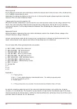
For each element the following characteristics are available:
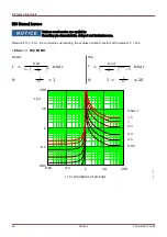
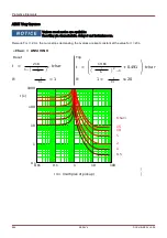
DEFT (UMZ) –
Definite Time-Overcurrent
NINV (IEC/AMZ) –
IEC Normal Inverse
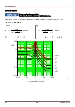
VINV (IEC/AMZ) –
IEC Very Inverse
LINV (IEC/AMZ) –
IEC Long Time Inverse
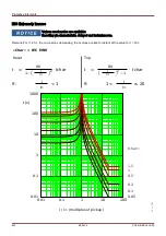
EINV (IEC/AMZ) –
IEC Extremely Inverse
MINV (ANSI/AMZ) –
ANSI Moderately Inverse
VINV (ANSI/AMZ) –
ANSI Very Inverse
EINV (ANSI/AMZ) –
ANSI Extremely Inverse
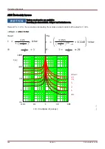
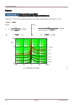
RINV –
R Inverse
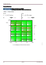
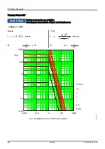
Thermal Flat
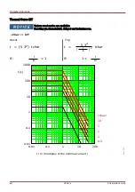
IT
I2T
I4T
Explanation:
By using the projecting parameters each of the overcurrent protective elements can be defined as
»forward«,
»reverse« or »non-directional«. The forward or reverse direction is based on the characteristic angle for the phase
direction specified by the field parameter
»I MTA«. No directional information will be taken into account if the current
protective element is planned as
»non-directional«
679
MCDLV4
DOK-HB-MCDLV4-2E
t = Tripping delay
t-char = Time multiplier/tripping characteristic factor . The setting range depends
on the selected tripping curve.
I = Fault current
I> = If the pickup value is exceeded , the module/element starts to time out to trip .
Summary of Contents for HighPROtec MCDLV4
Page 3: ...Order Code Order Code 3 MCDLV4 DOK HB MCDLV4 2E...
Page 47: ...Installation and Connection 47 MCDLV4 DOK HB MCDLV4 2E...
Page 164: ...Input Output and LED Settings 164 MCDLV4 DOK HB MCDLV4 2E...
Page 433: ...Parameters 433 MCDLV4 DOK HB MCDLV4 2E...
Page 457: ...Device Parameters 457 MCDLV4 DOK HB MCDLV4 2E...
Page 473: ...Blockings 473 MCDLV4 DOK HB MCDLV4 2E...
Page 988: ...Protective Elements 988 MCDLV4 DOK HB MCDLV4 2E P P Q P Q P Q Q Q P S S...
Page 989: ...Protective Elements 989 MCDLV4 DOK HB MCDLV4 2E Pr Q P Q P Qr...
Page 1023: ...Protective Elements 1023 MCDLV4 DOK HB MCDLV4 2E...

