Protective Elements
AR States
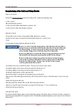
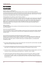
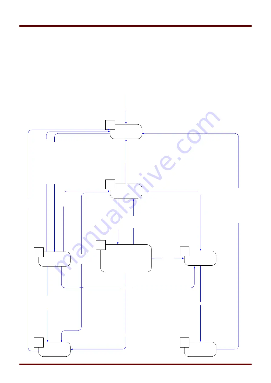
The following diagram shows the state transitions between the various states of the autoreclosure function. This
diagram visualizes the run time logic and timing sequence according to the state transition direction and the events
which trigger the transitions.
State transition diagram
784
MCDLV4
DOK-HB-MCDLV4-2E
Standby
1
Ready
3
Lockout
6
t-Blo after CB man ON
2
t-Reset Lockout
7
Blocked
5
AR Cycle
Start
t-dead
t-Run2Ready
4
Lock=True
Initiate AR
In
itia
te
Fc
=T
ru
e
su
cc
es
sf
ul
C
B=
Po
s
O
N
Lock=True
C
B=
Po
s
O
N
t-B
lo
a
fte
r C
B
m
an
O
N=
tim
er
e
la
ps
ed
Reset Lockout=True
t-R
es
et
L
oc
ko
ut
=t
im
er
e
la
ps
ed
Bl
o=
Fa
ls
e
C
B=
Po
s
O
FF
&
t-B
lo
a
fte
r C
B
m
an
O
N=
tim
er
e
la
ps
ed
Bl
o=
Tr
ue
Blo=True
AR
.B
lo
=T
ru
e
Lock=True
CB=Pos OFF
Summary of Contents for HighPROtec MCDLV4
Page 3: ...Order Code Order Code 3 MCDLV4 DOK HB MCDLV4 2E...
Page 47: ...Installation and Connection 47 MCDLV4 DOK HB MCDLV4 2E...
Page 164: ...Input Output and LED Settings 164 MCDLV4 DOK HB MCDLV4 2E...
Page 433: ...Parameters 433 MCDLV4 DOK HB MCDLV4 2E...
Page 457: ...Device Parameters 457 MCDLV4 DOK HB MCDLV4 2E...
Page 473: ...Blockings 473 MCDLV4 DOK HB MCDLV4 2E...
Page 988: ...Protective Elements 988 MCDLV4 DOK HB MCDLV4 2E P P Q P Q P Q Q Q P S S...
Page 989: ...Protective Elements 989 MCDLV4 DOK HB MCDLV4 2E Pr Q P Q P Qr...
Page 1023: ...Protective Elements 1023 MCDLV4 DOK HB MCDLV4 2E...

