Protective Elements
Setting the Thresholds
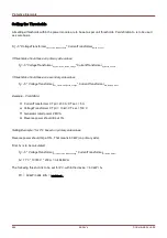
All settings/thresholds within the power module are to be set as per unit thresholds. Per definition S
n
is to be used
as scale basis.
S
n
=√3* VoltageTransformer
Line-to-Line_Rated_Voltage
* CurrentTransformer
Rated_Current
If thresholds should base on primary side values:
S
n
=√3* VoltageTransformer
Pri_Line-to-Line_Rated_Voltage
* CurrentTransformer
Pri_Rated_Current
If thresholds should base on secondary side values
S
n
=√3* VoltageTransformer
Sec_Line-to-Line_Rated_Voltage
* CurrentTransformer
Sec_Rated_Current
Example – Field Data
CurrentTransformer CT pri =200 A; CT sec = 5 A
VoltageTransformer VT pri = 10 kV; VT sec =100 V
Generator rated power 2 MVA
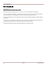
Reverse power should trip at 3%.
Setting Example 1 for Pr> based on primary side values
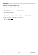
Reverse power should trip at 3%. That means 60 kW (on primary side).
First S
n
is to be calculated:
S
n
=√3 * VoltageTransformer
Pri_Line-to-Line_Rated_Voltage
* CurrentTransformer
Pri_Rated_Current
S
n
= 1.73 * 10000 V * 200 A = 3.464 MVA
The following threshold is to be set for Pr> within the device = 60 kW / S
n
Pr> = 60 kW/ 3464 kVA = 0,0173 S
n
986
MCDLV4
DOK-HB-MCDLV4-2E
Summary of Contents for HighPROtec MCDLV4
Page 3: ...Order Code Order Code 3 MCDLV4 DOK HB MCDLV4 2E...
Page 47: ...Installation and Connection 47 MCDLV4 DOK HB MCDLV4 2E...
Page 164: ...Input Output and LED Settings 164 MCDLV4 DOK HB MCDLV4 2E...
Page 433: ...Parameters 433 MCDLV4 DOK HB MCDLV4 2E...
Page 457: ...Device Parameters 457 MCDLV4 DOK HB MCDLV4 2E...
Page 473: ...Blockings 473 MCDLV4 DOK HB MCDLV4 2E...
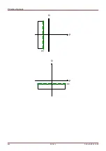
Page 988: ...Protective Elements 988 MCDLV4 DOK HB MCDLV4 2E P P Q P Q P Q Q Q P S S...
Page 989: ...Protective Elements 989 MCDLV4 DOK HB MCDLV4 2E Pr Q P Q P Qr...
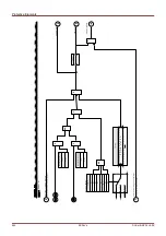
Page 1023: ...Protective Elements 1023 MCDLV4 DOK HB MCDLV4 2E...

