Manual 37442B
LSG - Load Share Gateway
© Woodward
Page 23/32
CAN Bus Topology
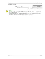
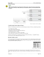
NOTE
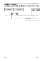
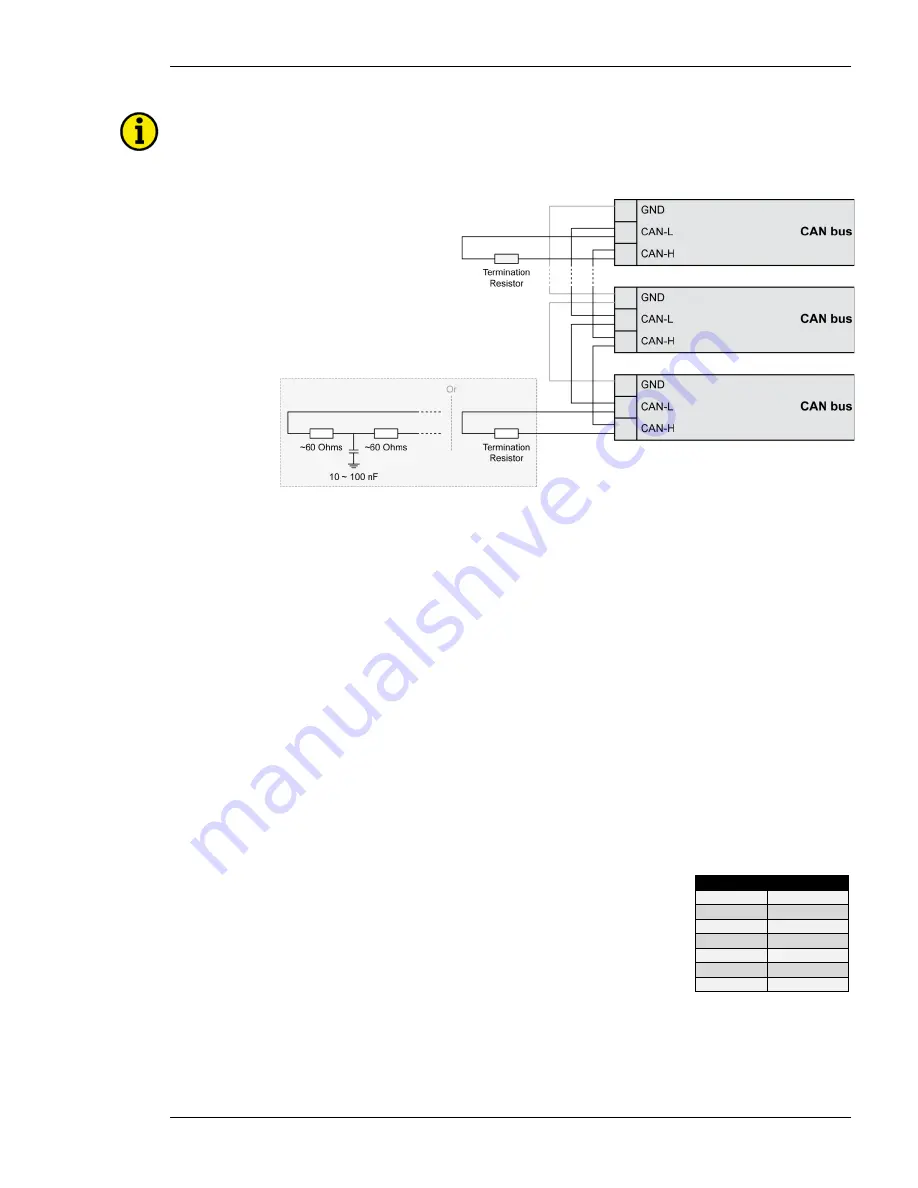
Please note that the CAN bus must be terminated with a resistor, which corresponds to the impedance
of the cable (e.g. 120 Ohms, 1/4 W) at both ends. The termination resistor is connected between CAN-H
and CAN-L.
Figure 4-7: Interfaces - CAN bus - termination
Troubleshooting Possible CAN Bus Problems
If data is not transmitting on the CAN bus, check the following for common CAN bus communication problems:
•
A T-structure bus is utilized
•
CAN-L and CAN-H are interchanged
•
Not all devices on the bus are using identical baud rates
•
Terminating resistor(s) are missing
•
The configured baud rate is too high for wiring length
•
The CAN bus cable is routed in close proximity with power cables
Woodward recommends the use of shielded, twisted-pair cables for the CAN bus (i.e.: Lappkabel Unitronic
LIYCY (TP) 2×2×0.25, UNITRONIC-Bus LD 2×2×0.22).
Maximum CAN Bus Length
The maximum length of the communication bus wiring is dependent on the configured baud rate. Refer to Table
4-6 for the maximum bus length (Source: CANopen; Holger Zeltwanger (Hrsg.); 2001 VDE VERLAG GMBH,
Berlin und Offenbach; ISBN 3-8007-2448-0).
Baud rate Max. length
1000 kbit/s 25 m
800 kbit/s
50 m
500 kbit/s
100 m
250 kbit/s
250 m
125 kbit/s
500 m
50 kbit/s
1000 m
20 kbit/s
2500 m
Table 4-6: Maximum CAN bus length
The maximum specified length for the communication bus wiring might not be achieved if poor quality wire is
utilized, there is high contact resistance, or other conditions exist. Reducing the baud rate may overcome these is-
sues.

