Manual 37442B
LSG - Load Share Gateway
Page 28/32
© Woodward
Chapter 6.
Operation
Status LEDs
≡≡≡≡≡≡≡≡≡≡≡≡≡≡≡≡≡≡≡≡≡≡≡≡≡
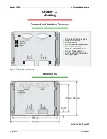
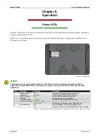
The three LEDs indicate the status of the module. The LEDs assist maintenance personnel in quickly identifying
wiring or communication errors.
A LED test is exercised at power-up. After power up the LEDs are building a “running light” until the correct
CAN baud rate is found.
Figure 6-1: Status LEDs
NOTE
The direction of the running light indicates, if the LSG is for active (light is running from LED1 to
LED3 ) part number 8440-1075 or reactive power (light is running from LED3 to LED1 ) part number
8440-1074.
LED
Function
Condition
Indication
1
easYgen Status
(CAN bus)
Off
No valid CAN bus messages are received
Toggling
Valid CAN bus messages are received
2
EGCP-2 Status
(RS-485) /
GCP/MFR Status
(CAN) / Analog line
Off
No RS-485 messages are received /
Analog line is on high impedance
Toggling
(RS-485 or CAN)
RS-485 or CAN messages are received
On (Analog)
Analog: LSG is sharing load on the analog line
3
Error indication
Off
The LSG detects no bus communication error
On
At least one device on the bus (RS-485 / CAN) is missing
Table 6-1: Outlines the indicator condition and the corresponding status after the baud rate is found.

