background image

Manual 37442B 

LSG - Load Share Gateway 


© Woodward 

Page 11/32 

Application Overview 

≡≡≡≡≡≡≡≡≡≡≡≡≡≡≡≡≡≡≡≡≡≡≡≡≡


The LSG is available in two different types: 


Active power load share (P) 


Reactive power load share (Q) 


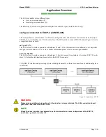
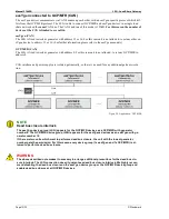
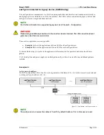
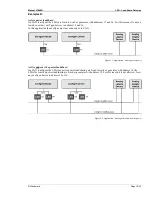
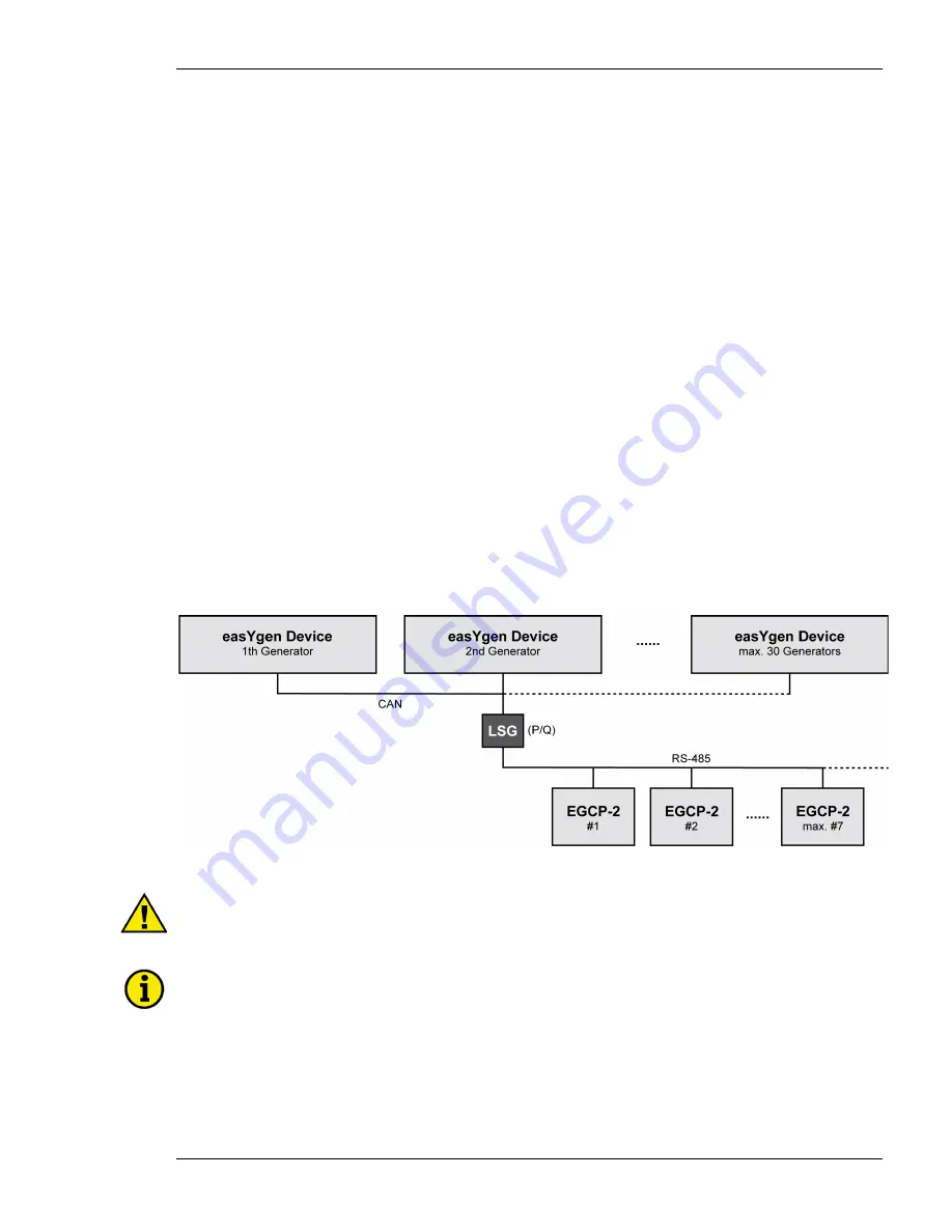
The following figures show application examples for both LSG types (marked with P or Q). 


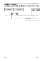
easYgen connected to EGCP-2 (CAN/RS-485) 


The easYgen devices communicate via CAN bus among each other and therefore can´t communicate directly to 

EGCP-2 devices which have no CAN bus interface. The LSG is able to connect EGCP-2 and easYgen devices in 

a single load share network. 


easYgen (CAN) 

The LSG is fixed to work as generator with address 15 and 16. For this reason it is not allowed, to set any other 

easYgen device to address 15 or 16. (For further information please refer to the easYgen manuals) 


EGCP-2 (RS-485) 

The LSG is fixed to work as generator with address 8. For this reason it is not allowed, to set any EGCP-2 to ad-

dress 8. (For further information please refer to the EGCP-2 manuals) 


CAN, RS-485 interface and power supply are isolated galvanically, so there is no need for any additional galvan-

ic isolation. 


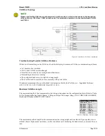
Figure 2-1: Application – EGCP-2 


WARNING


Please arrange additional precautions for the dead bus closure interlock. The LSG connection doesn´t 

guarantee a dead bus closure interlock. 


NOTE 

All easYgen devices which are allowed to perform a dead bus closure, independent of the EGCP-2, 

must have a generator number <15. 


Summary of Contents for Load Share Gateway

Page 1: ...37442B Manual Software Version 1 xxxx Manual 37442B Load Share Gateway LSG ...

Page 2: ...ff before disconnecting the battery from the system Electronic controls contain static sensitive parts Observe the following precautions to prevent dam age to these parts Discharge body static before handling the control with power to the control turned off contact a grounded surface and maintain contact while handling the control Avoid all plastic vinyl and Styrofoam except antistatic versions ar...

Page 3: ... 09 07 29 TE Minor corrections B 10 04 08 TE Minor corrections Design and graphics adjustments New features Requirements Load Share Gateway LSG with device revision A or higher New application mode Load sharing of easYgen devices and GCP MFR devices supported Refer to easYgen connected to GCP MFR CAN on page 12 for details ...

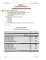
Page 4: ...rminal and Interface Overview CHAPTER 3 HOUSING 16 16 Dimensions 16 Power Supply CHAPTER 4 CONNECTION 18 18 Analog Load Share 19 Interfaces 20 RS 485 Serial Interfaces 20 CAN Bus Interface 22 Bus Shielding 24 LSG Configuration CHAPTER 5 CONFIGURATION 25 25 easYgen Configuration 25 easYgen LSG Display Information 26 EGCP 2 Configuration 27 GCP MFR Configuration 27 Status LEDs CHAPTER 6 OPERATION 28...

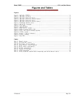
Page 5: ...igure 4 3 RS 485 interface overview 20 Figure 4 4 RS 485 Connection EGCP 2 LSG 20 Figure 4 5 RS 485 connection for half duplex operation 21 Figure 4 6 CAN bus overview 22 Figure 4 7 Interfaces CAN bus termination 23 Figure 4 8 Interfaces shielding 24 Figure 6 1 Status LEDs 28 Tables Table 1 1 Manual overview 7 Table 4 1 Conversion chart wire size 18 Table 4 2 Power supply terminal assignment 18 Ta...

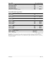
Page 6: ... 3100 3200 Package P2 Software Version 1 12xx 1 13xx easYgen 3100 3200 Installation 37414 GR37414 easYgen 3100 3200 Configuration 37415 GR37415 easYgen 3100 3200 Operation 37416 GR37416 easYgen 3100 3200 Application 37417 easYgen 3100 3200 Interfaces 37418 easYgen 3100 3200 Parameter List 37420 GR37420 easYgen 3200 Brief Operation Information 37399 GR37399 easYgen 3100 Brief Operation Information ...

Page 7: ...0 Series GCP 30 Installation 37364 GR37364 GCP 30 Configuration 37365 GR37365 GCP 30 Operation 37238 GR37238 GCP 30 Application 37240 GR37240 GCP 30 Rental GCP 30 Installation 37366 GR37366 GCP 30 Configuration 37367 GR37367 GCP 30 Operation 37238 GR37238 GCP 30 Application 37240 GR37240 EGCP 2 Series EGCP 2 Installation and Operation 26076 26174 EGCP 2 Application 26086 26175 EGCP 2 Communication...

Page 8: ...ward Overview The Load Share Gateway LSG is a next generation communication converter specifically designed to operate the easYgen 2000 easYgen 3000 Series and legacy devices RS 485 bus or analog load share line coupled in one single load share network ...

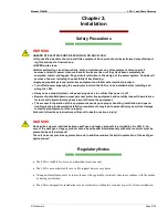
Page 9: ...protective equipment and carefully inspect the work area for tools and objects that may have been left inside the equipment The successful operation of this equipment depends upon proper handling installation and opera tion Neglecting fundamental installation requirements may lead to personal injury as well as damage to electrical equipment or other property Failure to follow these instructions wi...

Page 10: ...t unless absolutely necessary If you must remove the PCB from the control cabinet follow these precautions Make sure that the unit is completely de energized all connectors have to be pulled off Do not touch any part of the PCB except the edges Do not touch the electrical conductors connectors or components with conductive devices or with bare hands When replacing a PCB keep the new PCB in the pla...

Page 11: ...ith address 15 and 16 For this reason it is not allowed to set any other easYgen device to address 15 or 16 For further information please refer to the easYgen manuals EGCP 2 RS 485 The LSG is fixed to work as generator with address 8 For this reason it is not allowed to set any EGCP 2 to ad dress 8 For further information please refer to the EGCP 2 manuals CAN RS 485 interface and power supply ar...

Page 12: ... GCP MFR to address 8 CAN interface and power supply are isolated galvanically so there is no need for any additional galvanic isola tion Figure 2 2 Application GCP MFR NOTE Dead bus closure interlock The easYgen device group LSG appears for the GCP MFR devices as a GCP MFR with generator number 8 The GCP MFR device group LSG appears for the easYgens devices as an easYgen with ge nerator number 16...

Page 13: ... dead bus closure interlock There are two application scenarios possible Examples A shows the applications with one LSG for all easYgen devices Examples B shows the applications with one LSG for each easYgen devices To decide which setup is to prefer in the application different aspects for operation and safety should be re garded CAN Analog Line and power supply are isolated galvanically so there...

Page 14: ...tive power loadsharing is fixed to work as generator with address 16 the LSG for reactive power loadsharing to work as generator with address 15 For this reason it is not allowed to set any easYgen to address 15 or 16 reactive power loadshare Figure 2 4 Application analog active and reactive power ...

Page 15: ...16 In this application the easYgen must not connected via CAN Figure 2 5 Application analog active power Active and On CAN easYgen the LSGs for active power loadsharing are fixed to work as generator with address 16 the LSGs for reactive power loadsharing to work as generator with address 15 For this reason it is not allowed to set any easYgen device to address 15 or 16 reactive power loadshare Fi...

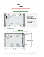
Page 16: ...face Overview 1 Power terminal block socket 2 RS 485 connector 3 CAN connector 4 Analog terminal block socket 5 Error indication LED 6 RS 485 GCP MFR CAN Analog Status Indicator 7 easYgen CAN Communica tion Status LED Figure 3 1 Terminal and interface overview Dimensions Hole Size 4x3 12 mm 375 ...

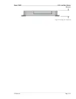
Page 17: ...Manual 37442B LSG Load Share Gateway Woodward Page 17 32 Figure 3 2 Housing LSG dimensions ...

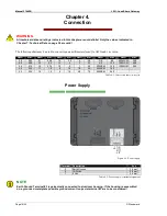
Page 18: ...5 4 25 3 0 95 600MCM 300 28 0 08 20 0 5 12 4 2 35 4 0 120 750MCM 400 26 0 14 18 0 75 10 6 1 50 300MCM 150 1000MCM 500 24 0 25 17 1 0 8 10 1 0 55 350MCM 185 22 0 34 16 1 5 6 16 2 0 70 500MCM 240 Table 4 1 Conversion chart wire size Power Supply Figure 4 1 Power supply Terminal Description Amax 3 Earth Ground 2 5 mm 2 12 24Vdc 2 5 mm 1 0 Vdc 2 5 mm Table 4 2 Power supply terminal assignment NOTE Ear...

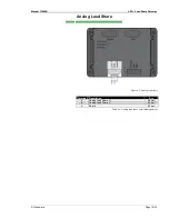
Page 19: ...are Gateway Woodward Page 19 32 Analog Load Share Figure 4 2 Analog load share Terminal Description Amax 6 Analog Load Share V 2 5 mm 5 Analog Load Share V 2 5 mm 4 Shield 2 5 mm Table 4 3 Analog load share terminal assignment ...

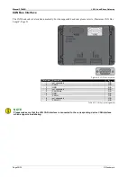
Page 20: ...ure 4 3 RS 485 interface overview Terminal Description Amax 1 not connected N A 2 RS 485 N A 3 not connected N A 4 not connected N A 5 GND N A 6 not connected N A 7 RS 485 N A 8 not connected N A 9 not connected N A Table 4 4 RS 485 interface pin assignment Figure 4 4 RS 485 Connection EGCP 2 LSG ...

Page 21: ...o EGCP 2 manual 26076 26174 Installation and Operation Chapter 3 Electrical Instal lation and Specifications This manual describes how the bus needs to be terminated Is the LSG at the end of the RS 485 bus a terminating resistor of 120 ohm needs to be connected to the Sub D connector The EGCP 2 must be configured via DIP switches according to the manual ...

Page 22: ...AN Bus Length Page 23 Figure 4 6 CAN bus overview Terminal Description Amax 1 not connected N A 2 CAN L N A 3 GND N A 4 not connected N A 5 CAN Shield N A 6 GND N A 7 CAN H N A 8 not connected N A 9 CAN VCC N A Table 4 5 CAN bus pin assignment NOTE Please make sure that the LSG CAN interface is connected to the corresponding device CAN interface which supports load sharing ...

Page 23: ...ng length The CAN bus cable is routed in close proximity with power cables Woodward recommends the use of shielded twisted pair cables for the CAN bus i e Lappkabel Unitronic LIYCY TP 2 2 0 25 UNITRONIC Bus LD 2 2 0 22 Maximum CAN Bus Length The maximum length of the communication bus wiring is dependent on the configured baud rate Refer to Table 4 6 for the maximum bus length Source CANopen Holge...

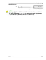
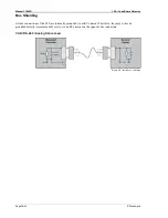
Page 24: ...s Shielding All bus connections of the LSG are internally grounded via an RC element Therefore they may either be grounded directly recommended or also via an RC element on the opposite bus connection CAN RS 485 Analog Share Load Figure 4 8 Interfaces shielding ...

Page 25: ... POW R CON R 20 67k P 0 5V 0 to 100 2 7 Prepared3 R 25 00k P 5 5V 0 to 100 2 8 Prepared3 R 25 00k P 0 7V 0 to 100 2 9 GCP MFR CAN P Q 1 easYgens and GCP MFR share the same CAN bus 10 to 15 Not defined Table 5 1 easYgen configuration 1 Operation mode supports one LSG device This single device is able to share P and Q 2 If this setting is reactive power mode the voltage is representing a Q range 100...

Page 26: ...s closed if one or more EGCP 2 has a closed GCB If the LSG mode is set to 9 GCP MFR the icon LSG at the LDSS screen easYgen is twinkling if the CAN connection between easYgen and LSG is OK This icon is permanent if a GCP MFR is detected on the CAN bus The GCB icon shows closed if one or more GCP MFR has a closed GCB In analog mode LSG at the LDSS screen is permanent if the CAN connection between e...

Page 27: ...to disabled Please configure DIP switch of the EGCP 2s to a correct termination of the RS 485 The LSG is always slave If reactive power needs to be shared the parameters RATED KW and RATED KVAR must be con figured to the same values within the EGCP 2 GCP MFR Configuration With the exception of number 8 all generator numbers can be configured Generator number 8 is not al lowed because the LSG is us...

Page 28: ...number 8440 1075 or reactive power light is running from LED3 to LED1 part number 8440 1074 LED Function Condition Indication 1 easYgen Status CAN bus Off No valid CAN bus messages are received Toggling Valid CAN bus messages are received 2 EGCP 2 Status RS 485 GCP MFR Status CAN Analog line Off No RS 485 messages are received Analog line is on high impedance Toggling RS 485 or CAN RS 485 or CAN m...

Page 29: ... reac tive Load Share this will appear with address 15 Testing the EGCP 2 Network Communication If the connection between the EGCP 2 and the LSG is working properly and the easYgen is detected by the LSG the LSG is indicated on the EGCP 2 sequence display screen as an EGCP 2 Slave with device number 8 Testing the CAN Bus Communication GCP MFR If the connection between the GCP MFR and the LSG is wo...

Page 30: ... Vac Type Half duplex max 38 4kBaud Shield Termination internal R C against Ground Terminal 3 CAN bus interface isolated Isolation voltage 500 Vac Version CAN bus Internal line termination Not available Shield Termination internal R C against Ground Terminal 3 Analog Load Share Line isolated Isolation voltage 500 Vac Input Output type Analog voltage in output configurable Internal Resistance confi...

Page 31: ...2 6 Fc Lloyd s Register Vibration Test2 SAEJ1455 Chassis Data MIL STD 810F M514 5A Cat 4 Truck Trailer tracked restrained cargo Fig 514 5 C1 Shock Shock 40G Saw tooth pulse 11ms Standards EN 60255 21 2 MIL STD 810F M516 5 Procedure 1 Temperature Cold Dry Heat storage 30 C 22 F 80 C 176 F Cold Dry Heat operating 20 C 4 F 70 C 158 F Standards IEC 60068 2 2 Test Bb and Bd IEC 60068 2 1 Test Ab and Ad...

Page 32: ...se 29 70565 Stuttgart Germany Phone 49 0 711 789 54 0 Fax 49 0 711 789 54 100 stgt info woodward com Homepage http www woodward com Woodward has company owned plants subsidiaries and branches as well as authorized distributors and other authorized service and sales facilities throughout the world Complete address phone fax e mail information for all locations is available on our website www woodwa...

Reviews: