Manual 37352A
MFR 12 Packages - Protection Relay
Page 12/62
© Woodward
Measuring Inputs
≡≡≡≡≡≡≡≡≡≡≡≡≡≡≡≡≡≡≡≡≡≡≡≡≡
Current
WARNING
Prior to disconnecting the current transformer connections or the connections of the transformer
which are located at the unit, ensure that the transformer is short-circuited.
NOTE
Grounding of the secondary of a current transformer must always be single-sided.
Overcurrent, Line-to-Ground Protection (
Packages CP
/
51V
)
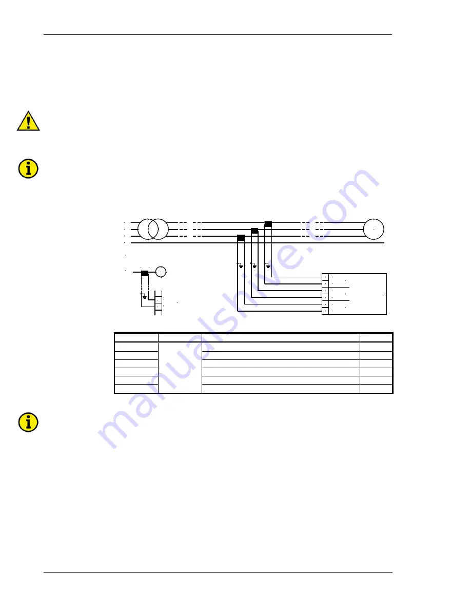
Detail:
Connection of the transformers
Generator
current
../1 A or ../5 A
L3
L2
L1
N
G
S2
S1
s2 (l)
s1 (k)
s2
L..
..
..
s1
L..
s1 (k)
s2 (l)
s1 (k)
s2 (l)
L2
s1 (k)
s2 (l)
42
43
40
41
44
45
L1
L3
G
Figure 3-3: Measuring inputs - current
Terminal Measurement Description
A
max
40
Generator current L1, transformer terminal s1 (k)
4 mm²
41
Generator current L1, transformer terminal s2 (l)
4 mm²
42
Generator current L2, transformer terminal s1 (k)
4 mm²
43
Generator current L2, transformer terminal s2 (l)
4 mm²
44
Generator current L3, transformer terminal s1 (k)
4 mm²
45
Transformer
../1 A or
../5 A
Generator current L3, transformer terminal s2 (l)
4 mm²
NOTE
The current transformers installation location will determine the protection area of the ground fault
monitoring.


