background image

Manual 37352A 

MFR 12 Packages - Protection Relay 


© Woodward 

Page 53/62 


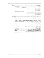
 Relay 

outputs ----------------------------------------------------------------------------------potential free


- Contact material....................................................................................................... AgCdO 
-  General purpose (GP) (V

Cont, relay output


AC .................................. 2.00 Aac@250 Vac 


DC ....................................2.00 Adc@24 Vdc 


0.36 Adc@125 Vdc 


0.18 Adc@250 Vdc 

-  Pilot duty (PD) (V

Cont, relay output


AC .................................................................. 


DC ....................................1.00 Adc@24 Vdc 


0.22 Adc@125 Vdc 


0.10 Adc@250 Vdc 

 Housing ---------------------------------------------------------------------------------------------------------  

-  Type........................................................................................... APRANORM DIN 43 700 
-  Dimensions (W × H × D) ....................................................................... 96 × 72 × 130 mm 
-  Front cutout (W × H)...................................................................91 [+1.0] × 67 [+0.7] mm 
 
- Wiring........... Screw-type terminals depending on connector 1.5 mm², 2.5 mm², or 4 mm² 
-  Recommended tightening torque.................[1.5 mm² / 2.5 mm²] 0.5 Nm, [4 mm²] 0.6 Nm 


use 60/75 °C copper wire only 


use class 1 wire only or equivalent 

- Weight ............................................................................................................approx. 800 g 

 Protection-------------------------------------------------------------------------------------------------------  

-  Protection system.................................................... IP42 from front with correct mounting 


IP54 from front with gasket (gasket: P/N 8923-1036) 


IP21 from back 

-  Front foil...................................................................................................insulating surface 
-  EMC test (CE) ...............................................tested according to applicable EN guidelines 
-  Listings ........................................................CE marking; UL listing for ordinary locations 


UL/cUL listed, Ordinary Locations, File No.: E231544 

- Marine-Approval ............................................................................................................ GL 


Summary of Contents for MFR 12

Page 1: ...37352A Manual Version 3 1xxx Manual 37352A MFR 12 Packages Protection Relay...

Page 2: ...ed off before disconnecting the battery from the system Electronic controls contain static sensitive parts Observe the following precautions to prevent dam age to these parts Discharge body static bef...

Page 3: ...2 Voltage 14 Discrete Inputs 15 Outputs 15 Relay Outputs Standard Packages 51V IvIkR 15 Interface 16 DPC Direct Configuration Interface 16 CHAPTER 4 FUNCTIONAL DESCRIPTION 17 Functional Table 17 Contr...

Page 4: ...Monitoring Packages CP 51V 50 51GN 39 Non Direct Ground Fault Monit via Displacement Volt Package IvIkR 41 Ground Fault Monitoring Measured Package IvIkR 43 Directional Ground Fault Monitoring Packag...

Page 5: ...s 15 Figure 5 1 Front panel 21 Figure 6 1 Diagram for independent time overcurrent monitoring 32 Figure 6 2 Inverse time overcurrent characteristic normal inverse 35 Figure 6 3 Inverse time overcurren...

Page 6: ...ackage list These packages can be found in the manual Each chapter headline points out if the described function is standard or part of a package Mounting B Flush mounting Current transformer secondar...

Page 7: ...The ground fault current is a direct measurement of the single phase ground current This measurement is suitable for line to ground monitoring in rigid or half rigid earthen mains e g in phase to phas...

Page 8: ...measured via cable type current transformer IE IE 9 Ground fault monitoring measured via current transformer IE IE 9 1 only when inverse time overcurrent monitoring with voltage restraint is disabled...

Page 9: ...ps cigarette packages cello phane wrappers vinyl books or folders plastic bottles etc away from the control modules and work area as much as possible 4 Opening the control cover may void the unit warr...

Page 10: ...6 Relay 7 Relay 2 Relay 1 Ready for operation 2005 10 13 MFR 12 Wiring Diagram r12ww 4105 ap skf 12 11 10 9 13 16 15 14 MFR 12 Multi Function Relay L1 L2 L3 N Displacement voltage via e n winding or...

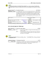
Page 11: ...rent coils undervoltage tripping units or auxiliary power contacts must be connected to a suitable interference suppressor The following chart may be used to convert square millimeters mm to AWG and v...

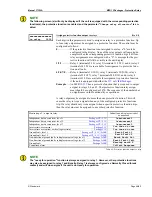
Page 12: ...current 1A or 5A L3 L2 L1 N G S2 S1 s2 l s1 k s2 L s1 L s1 k s2 l s1 k s2 l L2 s1 k s2 l 42 43 40 41 44 45 L1 L3 G Figure 3 3 Measuring inputs current Terminal Measurement Description Amax 40 Generat...

Page 13: ...ption Amax 40 Ie Ground current 4 mm 41 via Holmgreen Connection N 4 mm 40 Ie Ground current 4 mm 41 via cable type current transf N 4 mm 40 Ie Ground current 4 mm 41 via one pole transformer N 4 mm N...

Page 14: ...ransformer 1 Ve displacement voltage 2 5 mm 4 via zero point transformer N 2 5 mm Open e n winding 1 Ve displacement voltage 2 5 mm 4 via e n winding N 2 5 mm Reference Voltage Package 51V NOTE The re...

Page 15: ...Standard Packages 51V IvIkR A B Relay output Relay output external device external device external device C D E max 250 V AC Figure 3 9 Relay outputs Terminal Description Make contact Amax root closin...

Page 16: ...f live lines like phone lines will destroy the unit CAUTION The connection cable delivered with the DPC must be used between DPC and the unit to ensure proper functionality of the unit An extension or...

Page 17: ...ondirectional Ground fault current 1 2 1 1 0 1 Tripping Ve Ie blocked Line to ground fault Ve 1 1 1 0 Tripping Ie Line to ground fault 1 2 1 1 1 1 Tripping Ve Ie blocked Line to ground fault Ve By exc...

Page 18: ...cked via this discrete in put Non directional ground fault monitoring via displacement voltage External acknowledgement of the relays via the discrete input Blocking of protec tive functions remote ac...

Page 19: ...o relay 1 However other protective functions may also be assigned to relay 1 additionally Relay 1 is always configured as Normally Closed break contact and will de energize if the unit is not ready fo...

Page 20: ...Non directional ground fault via displacement voltage Package IvIkR E fault Ve Table 4 1 Alarm messages Alarm Acknowledgement A fault alarm is indicated by the Alarm LED By pressing the Clear button t...

Page 21: ...configuration cable there DPC MFR 1 L2 L23 L1 L12 L3 L31 Hz Reversible Display Operating Display Menu Digit Cursor Clear Alarm Converting Controlling Monitoring Select 14 1 2 13 12 4 3 5 7 6 Figure 5...

Page 22: ...olor Yellow Indication of the delta voltages If this LED is illuminated the values indicated on the display are the delta voltages phase phase 3 Operation Color Green Operation This LED is illuminated...

Page 23: ...is saved by pressing the Select push button once By pressing the button again the user causes the system to advance to the next configuration screen 13 Menu Digit Color none Menu Digit Automatic mode...

Page 24: ...Display in automatic mode first line measured values The following measured values are displayed depending on the Wye and Delta LEDs Packages CP The phase currents IL1 IL2 and IL3 are displayed Packag...

Page 25: ...user may scroll through the alarm messages that have occurred with the Menu button 00 00 yyyyyyyyyy Display in automatic mode second line alarm indication Alarm messages are shown on the bottom line...

Page 26: ...push button the scroll function will be activated allowing for the parameter screens to be advanced through more rapidly The control unit will permit the operator to reverse up to four previous scree...

Page 27: ...he parameters Configuration is blocked Code level CS1 Basic Service Level Factory password 0 0 0 1 This code level entitles the user to change selected controller set points enable auto clearing displ...

Page 28: ...figuration access is granted by entering the appropriate password Code level 1 2 If an incorrect code number has been entered configuration is blocked OFF Password protection is disabled Access to con...

Page 29: ...PC and the unit via the DPC Plug one side to the configuration plug of the unit and the other side to the COM1 port of your laptop PC other possibilities are described in the installation manual You...

Page 30: ...ere in kV This entry is used to show the system voltage in the display Example If a voltage of 110 V is measured without a potential transformer the secondary transformer voltage must be configured to...

Page 31: ...e exact value of the rated power is abso lutely vital Many measurement control and monitoring functions refer to this value Power Measurement Power measuring Power measurement one phase three phase Po...

Page 32: ...ring ON Independent time overcurrent monitoring ON OFF ON Independent time overcurrent monitoring is enabled and the subse quent screens of this function are displayed OFF Independent time overcurrent...

Page 33: ...onfigured rated system current refer to page 30 If this limit is reached or exceeded the unit outputs the message overcur rent 3 If a relay was assigned to this function in the relay manager that rela...

Page 34: ...rding to a defined curve the higher the measured current is According to IEC 255 three different characteristics are available Normal inverse 1 14 0 02 0 s t I I t p P Very inverse 1 5 13 s t I I t p...

Page 35: ...0 01 to 1 99s The time constant for tp is defined by this parameter Inv time ov cur Ip 0 0 In Inverse time overcurrent current constant Ip 0 1 to 3 0 In The current constant for Ip is defined by this...

Page 36: ...p 1 0 s tp 0 5 s tp 0 2 s tp 0 1 s tp 0 05 s tp 1 6 s I start Ip Figure 6 3 Inverse time overcurrent characteristic very inverse Extremely Inverse Ip In I start 1 1 x In 0 01 0 1 1 10 100 1000 1 10 10...

Page 37: ...ntained As a result the unit cannot maintain power in order to initiate a voltage independent overcurrent delay The voltage restraint functionality reduces the overcurrent threshold of the inverse tim...

Page 38: ...at the knee curve setting Ia knee point setting in 100 Ip If the knee curve setting is configured to 20 for example and the monitored voltage is lower than 20 of the rated voltage the adjusted value...

Page 39: ...monitoring ON OFF ON Ground fault monitoring is enabled The subsequent screens of this function are displayed OFF Ground fault monitoring is disabled The subsequent screens of this function are not d...

Page 40: ...tiating ground fault cur rent alarms levels 1 2 a lower release point is defined here If the control moni tors the current above the permissible limit the current must drop below that threshold and th...

Page 41: ...naccurate values caused by harmonics from being displayed If the ac tual sine wave of the ground current exceeds the configured threshold the alarm message E fault Ve is displayed This message cannot...

Page 42: ...ctions remote acknowledgement Earth fault Ve Response v 000 Threshold displacement voltage level 2 3 to 100 The displacement voltage threshold level 2 is defined by this parameter The per centage conf...

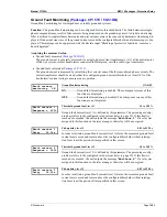
Page 43: ...to this function in the relay manager that relay will be energized Earth current 1 Delay 00 00s Pickup delay level 1 0 02 to 99 98 s In order to initiate a ground fault current level 1 alarm the measu...

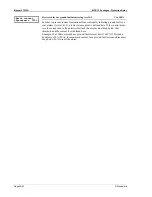
Page 44: ...the Earth fault 1 or Earth fault 2 limit the E fault Ve message will be issued after expiry of the configured delay time The current direction will not be taken into ac count This message may be suppr...

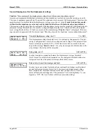
Page 45: ...nt monitoring is being performed in a compensated system Earth fault Ie Angle adj 000 Angle correction of the ground current 180 to 0 to 180 To monitor specific systems the phase angle monitoring can...

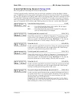
Page 46: ...cked with the discrete input Blocking of protective functions remote acknowledgement are only reset after the fault condition is no longer present Auto clearing Relays configured ON refer to Auto Ackn...

Page 47: ...Packages CP 51V Overcurr Time overcurrent 1 2 and 3 Inverse time overcurrent Package 51V Curr Inv Inverse time overcurrent with voltage restraint Package 51V Curr Inv Ground fault Standard Earth F Gr...

Page 48: ...the same The following is an example showing relays 1 through 3 Depending on the model purchased the unit may have up to 7 configurable relays The Packages 51V IvIkR enable to use 5 additional relays...

Page 49: ...to relays 2 4 and 7 That protective function relay assign ment should be configured as 2470 The sequence of the numbers has no significance in the functionality or operations A relay output may be as...

Page 50: ...cuit breaker must be disconnected at the unit circuit breaker The field rotation must be monitored for proper rotation Any absence of or incorrect connection of voltage measuring devices or other sign...

Page 51: ...mensions r1ww 3705 ab skf 50 mm 130 mm 96 mm 8 90 mm 130 mm 72 mm 65 mm 27 mm 35 mm Back view with connecting terminals Bottom view Back plate mounting optional please order brackets P N 8923 1023 Fro...

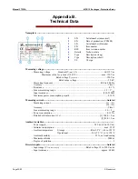
Page 52: ...40 0 to 80 0 Hz Accuracy Class 1 Resistance 0 1 Linear measuring range 1 3 Vrated Input resistance 1 0 21 M Maximum power consumption per path 0 15 W Measuring current isolated Measuring current 1 1...

Page 53: ...cutout W H 91 1 0 67 0 7 mm Wiring Screw type terminals depending on connector 1 5 mm 2 5 mm or 4 mm Recommended tightening torque 1 5 mm 2 5 mm 0 5 Nm 4 mm 0 6 Nm use 60 75 C copper wire only use cla...

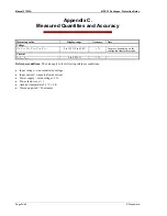
Page 54: ...VL23 VL31 0 to 125 V 0 to 65 kV 1 Accuracy depending on the configured transformer ratio Current IL1 IL2 IL3 0 to 9 999 A 1 Reference conditions The data apply to the following reference conditions I...

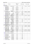
Page 55: ...ing BASIC DATA Software version SPRACHE LANGUAGE German English English G E G E Enter code number 0000 to 9999 Password Protection ON OFF ON 1 0 1 0 Define level 1 code 0000 to 9999 0001 Define level...

Page 56: ...sponse 10 to 300 120 Earth current 1 Delay 0 02 to 99 98 s 0 1 s Earth current 2 Response 10 to 300 160 Earth current 2 Delay 0 02 to 99 98 s 0 04 s Earth current Hysteresis 0 to 300 5 IvIkR Earth fau...

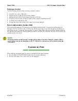
Page 57: ...ses your problem can be resolved over the phone If not you can select which course of action you wish to pursue based on the available services listed in this section Returning Equipment for Repair If...

Page 58: ...partment in Stuttgart 49 711 789 54 0 They will help expedite the processing of your order through our distributors or local service facility To expedite the repair process contact Woodward in advance...

Page 59: ...following international Woodward facilities to obtain the address and phone number of the facility nearest your location where you will be able to get information and service Facility Phone number USA...

Page 60: ...oll free or local phone numbers e mail us or use our website and refer ence technical support Product Training is available on site from several of our worldwide facilities at your location or from GE...

Page 61: ..._______________ Control see name plate Unit no and Revision P N ___________________ REV ____________ Unit type MFR 12 ___________________________________ Serial number S N ____________________________...

Page 62: ...e 29 70565 Stuttgart Germany Phone 49 711 789 54 0 Fax 49 711 789 54 100 stgt info woodward com Homepage http www woodward com power Woodward has company owned plants subsidiaries and branches as well...

Reviews: