Manual 37143A
MFR 15 - Protection Relay & Control
© Woodward
Page 57/119
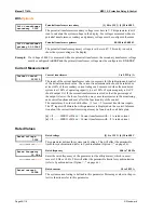
Power Factor Set Point
Pow.fact. contr.
Setpoint 0.00
Power factor controller set point
i0.70 to 1.00 to c0.70
The generator may be operated at a predefined power factor when operated in par-
allel with the mains. The power factor for mains parallel operation is defined by
this parameter. The designations "i" stands for inductive/lagging power factor (gen-
erator over excited) and "c" stands for capacitive/leading power factor (generator
under excited).
Setp. pow. fact.
min.value *O,O0
Set point "variable"
(only with
Option G
/
GU
)
Lower limit with variable power-factor set point
i0.70 to 1.00 to k0.70
The set value indicates the minimum set point value that can be reached with an ex-
ternal set point selection via that actuating signals "lower". The smaller voltage
value should be entered here.
Setp. pow. fact.
max.value *O,O0
Set point "variable"
(only with
Option G
/
GU
)
Upper limit with variable power-factor set point
i0.70 to 1.00 to k0.70
The set value indicates the maximum set point that can be reached with an external
selection of the set point via actuating signal "higher". The greater voltage value
should be entered here; otherwise, the assignment to terminals 6 and 7 ("higher"
and "lower" is reversed).
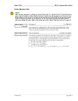
Setp. pow. fact.
Gradiant = 00V/s
Set point "variable"
(only with
Option G
/
GU
)
Slope of the power-factor potentiometer set point
0.01 to 0.30 /s
The effect of the increase indicates the speed (in volts per second) at which the
power factor set point value changes when selected using the "higher"/"lower" sig-
nals on the digital inputs via an actuating signal.
Setp. pow. fact.
Ramp = 00V/s
(only with
Option G
/
GU
)
Power-factor controller set point ramp
0.01 to 0.30 /s
The set point ramp indicates how rapidly (in volts per second) the power factor set
point is supposed to approach its limit value. The change is linear.


