Manual 37143A
MFR 15 - Protection Relay & Control
Page 84/119
© Woodward
xxxxxxxxxxxxxxxx
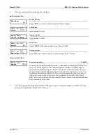
to relay 0000
Output of the protective units to the relays
0 to 3
Each digit in this parameter is used to assign one relay to a protective function. Up
to four relay outputs may be assigned to a protective function. The control may be
configured as follows:
0
....................If the protective function is not assigned to a relay, a "0" must be
configured in the display. None of the relay outputs will energize/de-
energize when the corresponding protective function trips if all four
relay assignments are configured with a "0". A message for the pro-
tective function will still be visible in the unit display.
1/2/3
..............Relay 1 (terminals 9/10), relay 2 (terminals 11/12/13), and/or relay 3
(terminals 14/15/16) are available for assignment to protective func-
tion on all units.
Example
.......A unit has a protective function that is required to output a signal to
relays 2 and 3. That protective function relay assignment should be
configured as 2300. The sequence of the numbers has no significance
in the functionality or operations.
A relay output may be assigned to more than one protective function. This will
cause the relay to issue a signal when any of the configured protective functions
trip. If a relay should only issue a signal when a specific protective function trips,
then the relay must not be assigned to any other protective function.
Monitoring of ... output to relay
Indication on display instead of
xxxxxxxxxx
Boost
Option PZ
Start next gen.
Overvoltage, level 1
Option U
Overvoltage 1
Overvoltage, level 2
Option U
Overvoltage 2
Undervoltage, level 1
Option U
Undervoltage 1
Undervoltage, level 2
Option U
Undervoltage 2
Asymmetry
Option U
Asymmetry
Overfrequency, level 1
Option U
Overfrequency 1
Overfrequency, level 2
Option U
Overfrequency 2
Underfrequency, level 1
Option U
Underfrequency 1
Underfrequency, level 2
Option U
Underfrequency 2
Phase shift
Option V
Phase jump
df/dt
Option D
df/dt
Independent time-overcurrent, level 1
Option IZ
Overcurrent 1
Independent time-overcurrent, level 2
Option IZ
Overcurrent 2
Independent time-overcurrent, level 3
Option IZ
Overcurrent 3
Overload
Option PM
Overload
Reverse/reduced power
Option PM
Reverse/min.pow.
Unbalanced load
Option PS
Unbalance load
Load shift, negative
Option ZW
Neg. power shift
Load shift, positive
Option ZW
Pos. power shift
Reactive power, capacitive
Option ZQ
Cap. react. pow.
Reactive power, inductive
Option ZQ
Ind. react. pow.
Power factor cosphi, level 1
Option ZC
cosphi 1
Power factor cosphi, level 2
Option ZC
cosphi 2
Busbar overvoltage
Option US
U> Busbar
Busbar undervoltage
Option US
U< Busbar
Busbar overfrequency
Option US
f> Busbar
Busbar underfrequency
Option US
f< Busbar
Centralized alarm
Collect response
Shutdown
Option W
/
O
/
B
Stop order
Table 6-2: Protective device output to relay
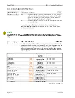
NOTE
The "ready for operation" function is always assigned to relay 1. However, other protective functions
may also be assigned to relay 1 additionally. Relay 1 is always configured as Normally Closed (break
contact) and will de-energize if the unit is not ready for operation.


