Manual 37143A
MFR 15 - Protection Relay & Control
© Woodward
Page 11/119
Chapter 3.
Installation
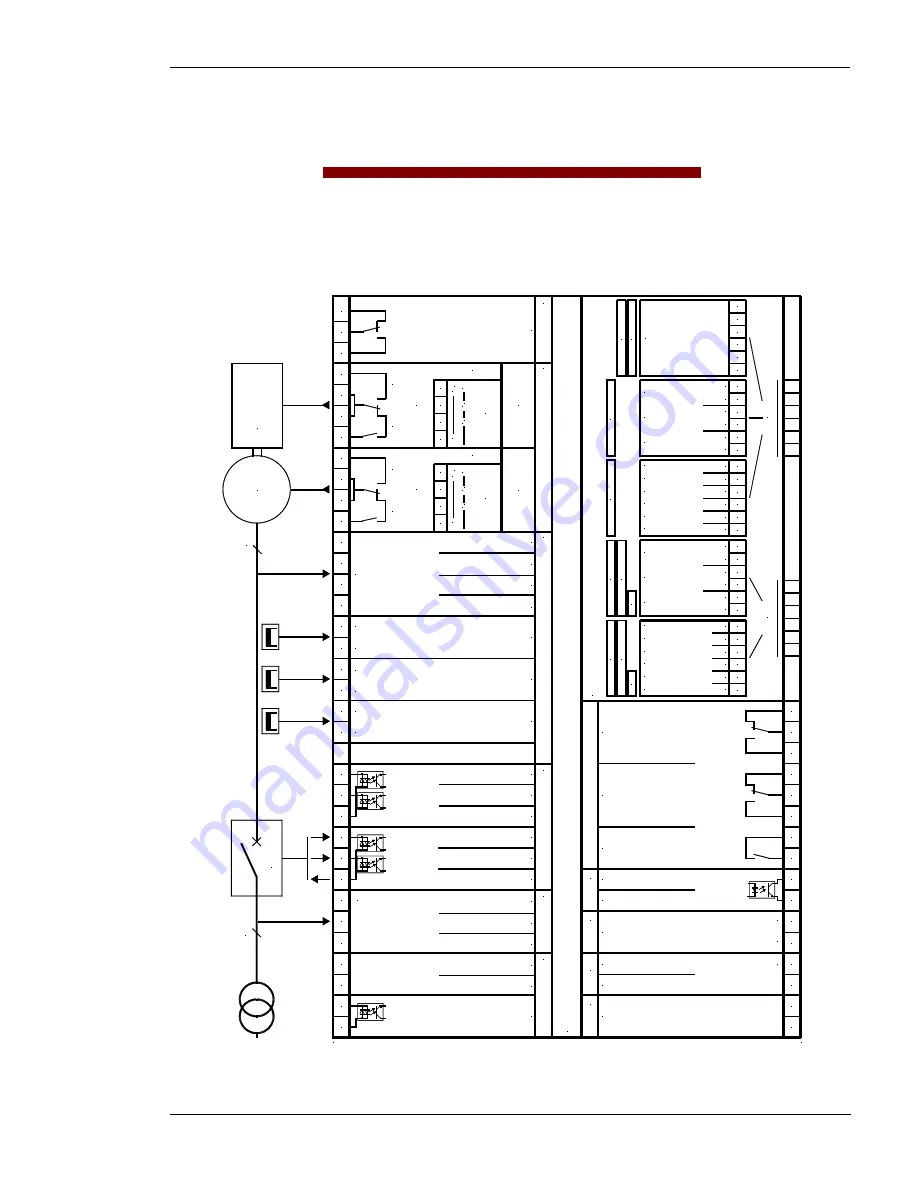
Wiring Diagram up to Version 1.9xx / 2.0xx
≡≡≡≡≡≡≡≡≡≡≡≡≡≡≡≡≡≡≡≡≡≡≡≡≡
G /
Y
Y
G /
Y
St
an
da
rd
Y
S
tan
dar
d
43
not measured
Printed 07/2001; subject to technical modifications.
3
5
7
8
6
71
70
CB
72
32
31
30
74
73
75
40
41
42
Synchronization voltage L2
Synchronization voltage L1
0 V DC
24 V DC
Synchronization voltage L3
Generator currrent L2
Generator currrent L1
Y: Isolated operation
G: Setpoint higher
Y: Release CB
G: Release Controller
Common
Common
Reply: CB is open
Y: [<2.0xx] free, [>2.1xx] Remote ack.
G: Setpoint lower
Measuring voltage
three-wire or
four-wire system
x1
x2
En
gi
ne
20
3
G
44
4
45
1
3
2
19
23
24
25
26
27
28
29
21
22
SPEE
D
ACT
IVE PO
W
ER
Th
ree-
po
si
tio
n
co
nt
ro
lle
r
An
al
og
co
nt
ro
lle
r
(P
ID
ch
ar
ac
teri
st
ic
)
(Generator voltage N)
Generator currrent L3
alternatively:
0
0
V
a
ra
is
e
20
19
23
24
25
26
Thr
ee-
posi
tion
cont
rol
ler
ra
is
e
lo
w
er
Generator voltage L1
Generator voltage L2
Generator voltage L3
I
I
0
I
a
a
a
EX
C
IT
AT
ION
VOL
TAG
E
REAC
TI
VE
P
O
W
ER
Anal
og c
ont
rol
ler
(P
ID
ch
ar
ac
teri
st
ic
)
SYNCHRONIZATION
Impulse or holding relay
alternatively:
V
a
21
22
lo
w
er
a
I
0
P
os
si
bl
e c
om
bin
at
io
ns
:
A
1/A
2/
A
3/
A
4+
S
..,
A
6,
A
8, S
..
52
Analog output 2
A8
A4
+/- 10 V
Reference point terminal 4
+/- 10 V
Auxiliary voltage
75 to 265 V AC or 90 to 300 V DC
Input/output Psum
Analog input (20 mA)
N
NC
W/
O
X
M
F
R
15 (
unt
il v
er
si
on 1.
9xx
/2.
1x
x)
E (open collector)
C (kWh or kvarh impulse)
A1
Relay 2
Relay 1
M
Relay 3
Analog output 1
Common 1 + 2
2001-07-25 MFR 15 Anschlußplan r15leo-2901-ap.skf
17
0
59
56
57
58
18
20 mA
60
12
61
11
10
9
50
51
0
13
16
15
14
+/- 20 mA
+/- 20 mA
+/- 20 mA
+/- 10 V
+/- 10 V
+/- 20 mA
+/- 20 mA
+/- 10 V
+/- 10 V
+/- 10 V
+/- 10 V
+/- 20 mA
Analog output 5
A2
A6
A3
A6
A8
Common 3 + 4
Analog output 3
Analog output 4
Analog output 1
Analog output 2
Analog output 3
Analog output 5
Analog output 6
Analog output 7
Analog output 8
Analog output 4
Common 5 + 6
Common 7 + 8
S.
.
S.
.
Analog output 6
Interface
RS-232, RS-422, RS-485
TTY, MOD bus slave
CAN bus, modem
Profi bus DP
84
Al
te
rn
at
iv
el
y
53
0
52
54
55
50
51
53
54
55
0
0
0
Al
te
rn
at
iv
el
y
81
82
83
81
82
83
84
85
86
0
0
00
0
X1
X2
X3
86
87
X4
X5
0
X6
[>2.1xx] Blocking of watchdog funct.
[<2.0xx/G] Blocking of watchdog funct. /
remote acknowledgment
x2
x1
x2
x1
Figure 3-1: Wiring diagram up to version 1.9xx / 2.0xx


