Manual 37143A
MFR 15 - Protection Relay & Control
Page 70/119
© Woodward
Independent Time-Overcurrent Monitoring (
Option IS
/
IZ
)
NOTE
All percentage values of the current refer to the rated current (page 44).
Function:
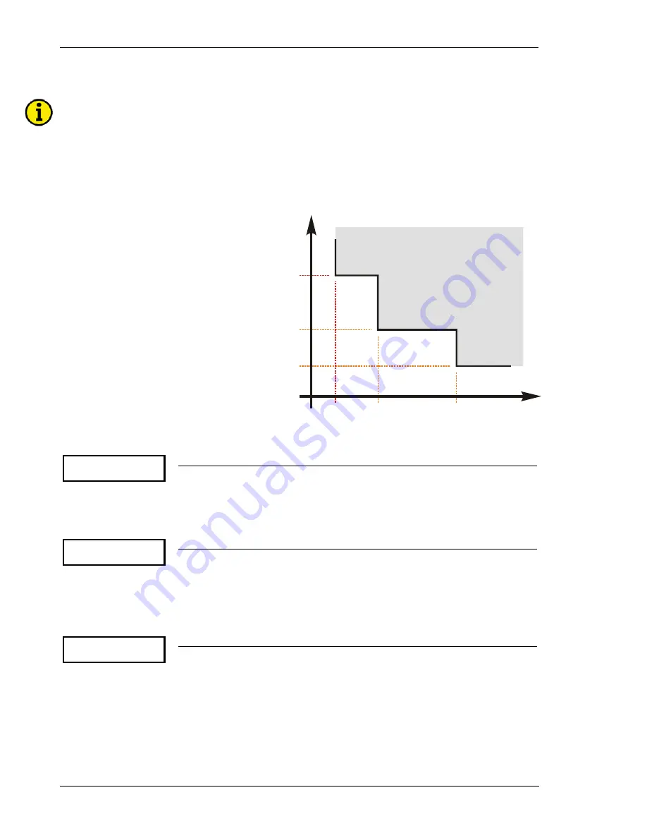
Current is monitored depending on parameter "Overcurrent Monitoring". The time-overcurrent alarm
contains three limits and can be setup as a step definite time overcurrent alarm as illustrated in the figure below.
Monitoring of the maximum phase current is performed in three steps. Every step can be provided with a delay
time independent of the other steps.
t [s]
SP3 [%/I
]
Rated
SP2 [%/I
]
Rated
SP1 [%/I
]
Rated
I
Rated
[%]
Protected Area
SP1 < SP2 < SP3
t
> t
> t
[SP1]
[SP2]
[SP3]
t
[SP3]
t
[SP2]
t
[SP1]
Figure 6-1: Diagram for independent time-overcurrent monitoring
Overcurrent
Monitoring ON
Independent time-overcurrent monitoring
ON/OFF
ON
................Independent time-overcurrent monitoring is enabled. The subsequent
screens of this function are displayed.
OFF
..............Independent time-overcurrent monitoring is disabled. The subsequent
screens of this function are not displayed.
Overcurrent 1
I> 000%
Threshold independent time-overcurrent, level 1
0 to 300 %
Overcurrent (level 1) is defined by this parameter. The percentage configured in
this parameter refers to the configured rated system current (refer to page 44). If
this limit is reached or exceeded, the unit outputs the message "
overcur-
rent 1
". If a relay was assigned to this function in the relay manager, that relay
will be energized.
Overcurrent 1
Delay 00.00s
Pickup delay, level 1
0.02 to 99.98 s
In order to initiate an overcurrent (level 1) alarm, the measured current must exceed
and remain above the configured level 1 threshold without interruption for at least
the period of time specified in this screen.


