Operation Manual 37107F
MFR 3 - Multi Function Relay
© Woodward
Page 21/165
Discrete Inputs
≡≡≡≡≡≡≡≡≡≡≡≡≡≡≡≡≡≡≡≡≡≡≡≡≡
CAUTION
Please note that the maximum voltages which may be applied at the discrete inputs are defined as fol-
lows. Voltages higher than those specified will destroy the hardware!
Maximum input range: +/-18 to 250 Vac.
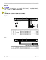
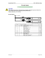
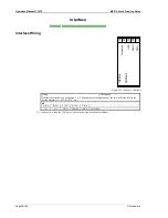
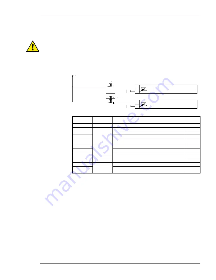
Control Inputs
Signal device
Digital input
B
A
+/-18 to 250 Vac/dc
CB
Reply
Digital input
D
C
3
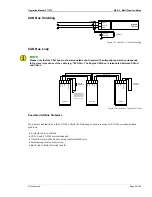
Figure 3-9: Discrete inputs - control inputs
Terminal Associated
common
Description
(according to DIN 40 719, part 3, 5.8.3)
A
max
A B
Make contact (NO)
3
7
Enable GCB
2.5 mm²
5
Switch set point value 1
↔
2
2.5 mm²
6
Enable monitoring
2.5 mm²
53
MFR 31: Enable externally
MFR 32: Enable MCB
2.5 mm²
34
33
Configuration blocked
2.5 mm²
35
Isolated controller ON
2.5 mm²
36
External acknowledgment
2.5 mm²
61
60
Block mains protection
2.5 mm²
C D
Break contact (NC)
4
7
Reply: GCB is open
2.5 mm²
54
MFR 31: Status: Isolated operation
MFR 32: Reply: MCB is open
2.5 mm²


