background image

Manual 26166V1 

MicroNet Simplex & MicroNet Plus 


Woodward 

111 

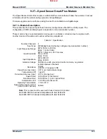
Table 9-3. Module Specification 


Analog Input Ratings 

Number of channels:  24 

Update time:  5 ms 

Input range:  0-25 mA or 0-5 V; software and hardware selectable 

Isolation: 

500 Vrms galvanic isolation to earth ground and control 
common, no galvanic isolation between channels 
60 dB CMRR 
200 Vdc common mode rejection voltage 

Input imp. (4-20 mA):  200 ohms 

Anti-aliasing filter: 

2 poles at 10 ms (CH01-22) 
2 poles at 5ms (CH23-24) 

Resolution: 16 

bits 

Accuracy:  Software calibrated to 0.1%, over 0-25 mA full scale 

Temp drift:  275 ppm/C, maximum 

Fuse:  100 mA fuse per channel located at FTM 

Time stamping:  5 ms resolution on low event and latch, and high event and latch 


Table 9-2. 4–20 mA Output Ratings 


Number of channels:  8 

Update time:  5 ms 

Output Driver:  linear 

Filter:  1 pole at 1ms plus 1pole at 0.25ms 

Current output:  4–20 mA 

Current output range:  0-25 mA 

Isolation:  500 Vrms galvanic isolation to earth ground and control 

common, no galvanic isolation between channels 

Max load resistance:  600 ohms (load + wire resistance) 

Resolution: 14 

bits 

Accuracy:  Software calibrated to 0.2% of 0-25 mA full scale 

Temperature drift:  125 ppm/C, maximum 


Source read back isolation:  60 dB CMRR, 200 Vdc common mode voltage rejection 

Read back Resolution 

Source: 12 

bits 

Return: 8 

bits 


Read back Accuracy 

Source:  0.5% of 0-25 mA full scale 

Return:  1% of 0-25 mA full scale 

Read back temp drift:  400 ppm/C, maximum 


Note:

 Item 5466-5025 (pending release in Q2 2016) must be used with Coder Version 5.08 or later. 


Coder 4.06 compatible versions: 


Item 5466-5026

 is backward compatible with P/N 5466-332 

Item 5466-5027

 is backward compatible with P/N 5466-425 


Note: 

Item 5466-5026 may be used in place of the 5466-315 if it is acceptable to have 5mS Anti-aliasing 

filter on A/I channels 23/24. (vs 10mS anti-aliasing filter). Please consult application engineering. 
 

Note

: AI and AO readback accuracy may be affected if the control is placed in a high electrical noise 

environment. 
 

Released

Summary of Contents for MicroNet Plus

Page 1: ...26166V1 Revision T 4 2018 Original Instructions MicroNet Simplex Digital Control MicroNet Plus Digital Control Manual 26166 consists of 3 volumes 26166V1 26166V2 26166V3 Installation and Operation Ma...

Page 2: ...o the equipment Any such unauthorized modifications i constitute misuse and or negligence within the meaning of the product warranty thereby excluding warranty coverage for any resulting damage and ii...

Page 3: ...le Replacement 26 3 4 Latent Fault Detection 26 CHAPTER 4 CHASSIS CONFIGURATIONS 27 4 1 MicroNet Plus 14 Slot Chassis 27 CHAPTER 5 POWER SUPPLIES 41 5 1 MicroNet Plus Chassis Power Supplies 41 5 2 Sim...

Page 4: ...odule 103 9 10 Voltage Input Module 103 9 11 8 Channel Voltage Input 0 10 Vdc Module 103 9 12 Current Output Modules 104 9 13 8Ch Current Output 4 20 mA Module 104 9 14 8Ch Current Output 0 1 mA Modul...

Page 5: ...Figure 4 12 Simplex MicroNet 12 Slot I O 38 Figure 4 13 Outline Drawing of MicroNet 12 Slot I O 39 Figure 4 14 Mounting Template of MicroNet 12 Slot I O Chassis 40 Figure 5 1 Power Supply Module 42 Fi...

Page 6: ...24 Vdc Discrete Input Output FTM 98 Figure 8 14 Discrete Input Interface Wiring with External Power Source to a Discrete Input with LEDs FTM 98 Figure 8 15 Discrete Input Module Block Diagram 99 Figu...

Page 7: ...on 90 Table 8 3 LED Indications of Failure 94 Table 8 4 Module Specification 97 Table 8 5 Module Specification 100 Table 9 1 Specification 105 Table 9 2 LED Indications of Failure 108 Table 9 3 Module...

Page 8: ...a SAFE condition of the controlled device CPU and I O module failures will drive the module into an IOLOCK state CPU failure will assert an IOLOCK signal to all modules and expansion racks to drive t...

Page 9: ...tatic versions around printed circuit boards Do not touch the components or conductors on a printed circuit board with your hands or with conductive devices To prevent damage to electronic components...

Page 10: ...ments Reference Section 15 of manual 26166V2 for considerations regarding the installation location and specific cabinet construction requirements Other European and International Compliance Complianc...

Page 11: ...ed in an IP54 minimum rated enclosure per self declaration to EN60079 15 Wiring must be in accordance with North American Class I Division 2 or European Zone 2 Category 3 wiring methods as applicable...

Page 12: ...uipment and is not to be used as metrology equipment All measurements need to be verified using calibrated equipment EXPLOSION HAZARD Do not connect or disconnect while circuit is live unless area is...

Page 13: ...Plus Woodward 11 Safety Symbols Direct Current Alternating Current Both Alternating and Direct Current Caution risk of electrical shock Caution refer to accompanying documents Protective conductor ter...

Page 14: ...prevents the possibility of changing system dynamics by adding additional code Control is always deterministic and predictable Dedicated inputs and outputs I O are available onboard for key control s...

Page 15: ...up to 14 VME slots per chassis The system may be expanded using copper or fiber cables to multiple chassis to accommodate additional system I O requirements 2 1 1 MicroNet Plus Configurations Table 2...

Page 16: ...m there are two CPU modules running the same application program receiving power from the same pins on the VME backplane and with access to the I O modules over the same VME bus The CPU modules commun...

Page 17: ...ables are connected directly to the faceplate of the communications module The following diagram shows the flow of analog and discrete inputs from the field to the application Figure 2 2 Input Flow Fi...

Page 18: ...application select the MICRONET14 or MICRONET8 chassis type and place a MicroNet Plus compatible CPU module in both A1 and A14 A8 slots Start up Load and start the application on each CPU using AppMa...

Page 19: ...is started 20 seconds after the first CPU this CPU will start up in the SIMPLEX mode When this occurs the CPU in A1 or A14 will remove the WATCHDOG then wait 20 seconds for the second CPU then continu...

Page 20: ...Single Remote RTN RTN1 SW MicroNet Plus Simplex 3 rack RTN2 SW Figure 2 6 MicroNet Plus Simplex System Diagrams 2 3 1 Redundant Power Supplies Two load sharing power supplies provide redundant power...

Page 21: ...e in one of the sensors connections cables FTMs or I O modules a valid input is still available Figure 2 10 Redundant Inputs This process can be expanded for triplicated inputs With triplicated inputs...

Page 22: ...hrough its redundant RTN port connections to the Remote RTN module 2 5 Module Replacement Chapter 15 contains Installation and Replacement procedures for VME Modules power supplies relay boxes and oth...

Page 23: ...Manual 26166V1 MicroNet Simplex MicroNet Plus Woodward 21 Example of MicroNet Plus fault information available from the CHASSIS14 status block Figure 2 11 CHAS_STAT Block Released...

Page 24: ...ers single CPU operation with up to 12 VME slots per chassis The system may be expanded to use multiple chassis to accommodate additional system I O requirements Different CPU options are available th...

Page 25: ...er Supply RMT XCVR A1 MicroNet Simplex 6 Exp XCVR XCVR TBOX FAN_2 FAN_1 FAN CPU A1 3 Slot Power Supply 3 Slot Power Supply MicroNet Simpl Main rack Single CPU Pe or Motorola x04 MAIN XCVR Figure 3 1 M...

Page 26: ...crete inputs from the field to the application Figure 3 2 Input Flow Figure 3 3 Output Flow 3 1 4 Redundant Inputs Two levels of I O signal redundancy are available The first involves wiring two exter...

Page 27: ...Pentium or Motorola x040 Assign communication and I O modules according to your application needs Compile and code your application using the Woodward GAP Coder tools For systems using the CPU5200 or...

Page 28: ...chassis is not recommended Remove power to the chassis before insertion or removal This process ensures that all I O modules will be placed into a known I O LOCK state upon power down 3 4 Latent Faul...

Page 29: ...sharing power supply is used Redundant Smart fans are used for early notification of fan failure Chassis temperature switches are built into the motherboard and trip at 65 C Redundant hot swappable CP...

Page 30: ...for monitoring fan status chassis temperature status and power supply status information The CPU slots also support operation of Redundant CPU s and the associated CPU Failover functions The CPU slots...

Page 31: ...y 24 Vdc Motherboard Power Redundant systems Not recommended for use Simplex systems This power may be used for local Ethernet switch power upon successful EMC testing Consider carefully the possibili...

Page 32: ...cable saddles that are not shown on the outline drawing below The PE ground connection point is located underneath the left side of the chassis To ensure compliance with the EMC certification all cha...

Page 33: ...the chassis Rack mounting is not recommended Figure 4 4 Mounting Template of MicroNet Plus 14 Slot I O Chassis 4 2 MicroNet Plus 8 Slot Chassis Figure 4 5 MicroNet Plus 8 Slot I O Chassis The MicroNe...

Page 34: ...ard I O connections are made through cables from the front of the boards to terminal blocks in the cabinet From a module connector standpoint any I O module can be installed in any of the slots design...

Page 35: ...d as Woodward P N 1641 1004 The system must be shut down to replace the fuses safely 24 Vdc Motherboard Power Redundant systems Not recommended for use Simplex systems This power may be used for local...

Page 36: ...e 4 7 Outline Drawing of MicroNet Plus 8 Slot Chassis 4 2 2 Installation Figure 4 8 shows the mounting template and fasteners to bulkhead mount the chassis Rack mounting is not recommended Figure 4 8...

Page 37: ...lar 6 slot chassis block Each block consists of a pre molded cage with a fan for cooling and a temperature switch for high temperature detection The chassis are cooled by forced air and either a modul...

Page 38: ...ys be in its designated slot Notes Add 2 5 cm to the depth dimension to account for the cable saddles that are not shown on the outline drawing below The PE ground connection point is located undernea...

Page 39: ...lve slots for CPU and I O input output modules Normally this allows one CPU module and eleven I O modules In addition to the 12 CPU I O slots two power supply positions are provided which allows for r...

Page 40: ...a motherboard inserted in the back of the assembly to make connections between the fans switches power supplies and control modules See Figure 4 13 The modules use the VERSAmodule Eurocard VME bus sta...

Page 41: ...ground connection point is located underneath the left side of the chassis To ensure compliance with the EMC certification all chassis mounting screws 8 32 M4 should be installed to properly ground th...

Page 42: ...MicroNet Plus Woodward 40 4 4 3 Installation Figure 4 14 shows the mounting template and fasteners to bulkhead mount the chassis Rack mounting is not recommended Figure 4 14 Mounting Template of Micro...

Page 43: ...nces the load to reduce heat and improve the reliability of the power supplies In the event that on supply needs to be replaced the recommended method for changing Power Modules is with the power off...

Page 44: ...y specifications For a particular system configuration use the MicroNet Power Program to calculate the output current requirements 24 V 5 V as a function of the Chassis CPUs and I O modules used in th...

Page 45: ...rrent 5 Vdc 22 0 A 65 C 28 A 60 C 32 A 55 C Holdup time 1 cycle 220 Vac Input Power Wiring A ground conductor connected to the chassis is required for safety The power supply grounding terminal s shou...

Page 46: ...m s source or consult Woodward for determining the minimum source requirements Table 5 1 provides each power supply s holdup time specification which is the time the supply will continue to operate wi...

Page 47: ...me between the indication of overtemperature LED illuminated and power supply shutdown If this LED is turned on verify that the fans in the power supply chassis are turning and free of dust and other...

Page 48: ...Each main power supply has four LEDs to indicate power supply health OK Input Fault Overtemperature and Power Supply Fault See MicroNet Simplex Power Supply Troubleshooting Section 5 5 for a descript...

Page 49: ...Power Supply Module Specifications Main PS Simplex 24 Vdc Input Operating Range 18 to 36 Vdc Nominal Voltage Rating 20 to 32 Vdc as on power supply label Maximum Current 29 5 A Maximum Power 531 W Inp...

Page 50: ...ating 10 A time delay Holdup Time 7 ms 120 Vdc Main PS Simplex 220 Vac Input High Voltage AC Operating Range 180 to 264 Vac 47 to 63 Hz Nominal Voltage Rating 200 to 240 Vac as on power supply label M...

Page 51: ...not equipped with input power switches For this reason some means of disconnecting input power to each main power supply must be provided for installation and servicing A circuit breaker meeting the...

Page 52: ...le 5 2 provides each power supply s holdup time specification which is the time the supply will continue to operate within specification after its input power is interrupted This information may be us...

Page 53: ...incorrect input voltages may permanently damage the power supply Once the input voltage is within the supply s input specifications this LED will turn off Refer to the power supply input specificatio...

Page 54: ...o contacting Woodward for technical assistance system problems can be more quickly and accurately assessed Is the input power within the range of the control s power supply input Is the input power fr...

Page 55: ...alternative topology Figure 6 1 Simple Teamed NIC Setup The teamed workstation has a single IP address NIC A and NIC B are the teamed adaptors sharing a single IP address Each NIC has a unique MAC add...

Page 56: ...ailover as a complete system However NO DIRECT CONNECTION to a MicroNet Plus CPU by a teamed NIC IP address should be part of the network configuration The workstation with un teamed NIC would become...

Page 57: ...Manual 26166V1 MicroNet Simplex MicroNet Plus Woodward 55 Figure 6 3 Teamed Network with No Direct Connection to MicroNet CPU Released...

Page 58: ...l marketplace For CPU module installation and replacement instructions see the instructions for installing and replacing the VME module in Chapter 15 Installation and Service and Section 9 4 3 Install...

Page 59: ...F RTN Network 172 20 x x ON RTN Network 10 250 x x Module Config Addr Switch Function 0 000 CPU MAIN CHASSIS 1 001 RTN CHASSIS X1 2 010 RTN CHASSIS X2 3 011 RTN CHASSIS X3 4 100 RTN CHASSIS X4 5 101 R...

Page 60: ...t 2 GbE2 192 168 128 20 Subnet Mask 255 255 255 0 Ethernet 1 ENET1 192 168 129 20 Subnet Mask 255 255 255 0 Ethernet 2 ENET2 192 168 130 20 Subnet Mask 255 255 255 0 Network Configuration Utility AppM...

Page 61: ...es to determine which CPU will be Syscon when application is commanded to start STATUS green when application is running IOLOCK off when application is running without errors STBY yellow when applicat...

Page 62: ...ir I O modules and the use of these RTN ports GAP block is RTN For redundant systems up to 2 Remote RTN modules may be installed into each expansion chassis When initialized by the main chassis CPU th...

Page 63: ...20 terminations at each end of the trunk line Drop cables connecting a device to the trunk line should be as short as possible and less than 6 meters It is recommended to design the network to be less...

Page 64: ...able manufacturer Turck and Belden are widely available in North America Turck Lumberg and Lapp Cable products are available in Europe All cables below are suitable for DeviceNet trunk and drop cablin...

Page 65: ...odes Every MicroNet Plus simplex control contains one CPU module located in the first I O slot of the MicroNet chassis A redundant configuration will also have a CPU located in the CPU2 location slot...

Page 66: ...LTH MONITOR MFT IOLOCK FAN MONITOR Control Status ARBITER BTO SYSCON 1 2V 1 5V 1 8V 2 5V 3 3V Isol 5V coms CAN 2 5V 2 5V 3 3V 3 3V LOCAL PWR MONITOR 5 0V_FAIL 3 3V_FAIL 2 5V_FAIL 1 8V_FAIL 1 5V_FAIL 1...

Page 67: ...itch settings before installing the module in the system and when troubleshooting CPU related issues If the CPU module is incorrectly configured for RTN mode Ethernet ports 1 and 2 are NOT active and...

Page 68: ...owerPC CPU5200 Module Front Panel LEDs LED Name Description RUN GR RD RUN RUN RESET GREEN RED Active RED when the user pushes the reset switch Active GREEN upon release and after the CPU Operating sys...

Page 69: ...a reset CPU1 and CPU2 Remote Reset Each CPU module will respond to a 24 V remote reset signal The chassis provides a terminal block with inputs RST1 RST1 RST2 and RST2 for wiring the remote reset sign...

Page 70: ...e shielded Cat 5 Ethernet cables SSTP are required for customer installations Cable length between the Main rack and RTN switch is 3 m 10 ft max Cable length between the RTN switch and Expansion rack...

Page 71: ...T operation is required from an expansion rack a CPU module must be used in place of the Remote RTN module and configured for an RTN using the Module Configuration Switch S2 as shown in section 6 2 2...

Page 72: ...ng braid or shielding braid and foil Cable type twisted pair cable 2x2 lines Bend Radius 20x diameter during installation or 7x diameter fixed position Signal attenuation 0 13 dB 100 ft 125 kHz maximu...

Page 73: ...Test Failure 2 4 HD1 Flash Test Failure 2 5 I2C Bus Test Failure 2 6 Module Installed in wrong slot 2 7 Main Chassis CPU switch must be set to 0 3 5 Remote RTN Rate Group 5 Slip 3 7 Remote RTN Rate G...

Page 74: ...structions for installing and replacing the VME module in Chapter 15 Installation and Service and Section 9 4 3 Installation This module will NOT automatically re initialize to a running state after r...

Page 75: ...Manual 26166V1 MicroNet Simplex MicroNet Plus Woodward 73 Figure 7 1 Remote RTN Module Released...

Page 76: ...fiber optic Ethernet switches It is required to use Woodward approved hardware for robust operation Table 7 1 System Redundancy Options Using Remote RTN Modules Redundancy Option CPU and Remote RTN mo...

Page 77: ...oNet Simplex MicroNet Plus Woodward 75 Figure 7 3 MicroNet Plus Redundant System copper 3 rack Figure 7 4 MicroNet Plus Redundant System copper 8 rack Figure 7 5 MicroNet Plus Redundant System fiber 2...

Page 78: ...guration as required Figure 7 7 MicroNet Plus Redundant System fiber 8 locations 7 1 3 Module Configuration Network Configuration No network configuration is required Only the RTN ports are active on...

Page 79: ...d for an RTN using the Module Configuration Switch S2 as shown in section 7 1 3 Module Configuration above It is recommended to verify proper switch settings before installing the module in the system...

Page 80: ...driven by the SYSCON where all I O modules are placed into a failsafe condition and outputs are driven to a known state FAULT CPU FAULT RED Actively flashes CPU fault codes as necessary WATCHD OG CPU...

Page 81: ...optic Ethernet switches are required to achieve communication and hardware redundancy Specific Ethernet switches have been tested and approved to obtain expansion chassis real time performance and re...

Page 82: ...s port is for VxWorks operating system use only and cannot be configured for application software use The communication settings are fixed at 38 4 kBd 8 data bits no parity 1 stop bit and no flow cont...

Page 83: ...ction 3 for information 7 3 Simplex Remote Transceiver XCVR Module Module Obsolete See Volume 3 Section 3 for information 7 4 Simplex Transceiver Accessories Module Obsolete See Volume 3 Section 3 for...

Page 84: ...Manual 26166V1 MicroNet Simplex MicroNet Plus Woodward 82 Figure 7 10 SIO Module Block Diagram Figure 7 11 SIO Module Released...

Page 85: ...an t be located at the end of a cable put it as close as possible to the ends Figure 5 17 is an example Figure 7 13 RS 485 Terminator Locations Termination is accomplished using a three resistor volta...

Page 86: ...way is to connect all circuit grounds to the shield and then connect the shield to earth ground at one point only If the latter method is used and there are non isolated nodes on the party line connec...

Page 87: ...ed Pair Cable without a Separate Signal Ground Wire 7 6 4 Troubleshooting 1 If the SIO module is not functioning or not functioning properly verify the cable connections 2 If the module is still not f...

Page 88: ...e cabinet housing the MicroNet system and are electrically continuous between the field termination and cabinet Routing coil and wetting voltage common wires with signal wires and shielding of DI DO f...

Page 89: ...Discrete cables See Figures 8 3 and 8 7 for examples of configurations Figure 8 2 Discrete Combo Module HDDIO Table 8 1 Module Specification Discrete Inputs Number of Channels 48 Update Time 5 ms Inpu...

Page 90: ...O Smart Plus module via two High Density Analog Discrete cables The top connector on the MicroNet Discrete I O Smart Plus module which is labeled J1 connects to J1 on the 48 24 Discrete FTM and J2 con...

Page 91: ...ee Figure 8 4 24 Vdc FTM only If an external 24 Vdc is used the common for the external 24 Vdc must be tied to the discrete input common see Figure 8 4 Power for contacts must be supplied by the contr...

Page 92: ...3 14 Ch 13 14 12 Mod 1 Ch 15 16 Ch 15 16 13 20 Mod 2 Ch 1 8 Ch 17 24 21 Mod 2 Ch 9 10 Ch 25 26 22 Mod 2 Ch 11 12 Ch 27 28 23 Mod 2 Ch 13 14 Ch 29 30 24 Mod 2 Ch 15 16 Ch 31 32 See Chapter 13 for field...

Page 93: ...ables See Figure 8 7 for an example of configuration Figure 8 7 Configuration 2 Two 24 12 Discrete FTMs Both the 48 discrete inputs and 24 discrete outputs are wired to the 24 12 Discrete FTM An exter...

Page 94: ...d power terminal blocks see Figure 8 8 If an external 24 Vdc is used the common for the external 24 Vdc must be tied to the discrete input common see Figure 8 8 Power for contacts must be supplied by...

Page 95: ...FTMs See Appendix A for part number Cross Reference for modules FTMs and cables 8 2 4 Troubleshooting Fault Detection Module Hardware Each MicroNet Discrete I O Smart Plus module has a red Fault LED...

Page 96: ...tion software determines the course of action in the event of a fault Microcontroller Faults The system monitors a software watchdog a hardware watchdog and a software watchdog on the VME bus communic...

Page 97: ...ions in Chapter 15 Installation for replacing the FTM Discrete Outputs If a discrete output is not functioning properly verify the following 1 Check the wiring for a loose connection on the terminal b...

Page 98: ...FTMs and the channels are labeled sequentially to correspond to their software locations for example discrete input 1 on the FTM will be discrete input 1 in the application software Figure 8 11 Discr...

Page 99: ...and the channels are labeled sequentially to correspond to their software locations for example discrete input 1 on the FTM will be discrete input 1 in the application software The FTM plugged into J...

Page 100: ...5 26 24Ret Channel 1 Channel 2 54 Channel 3 Channel 4 Power Source 1 21K Ohms Figure 8 14 Discrete Input Interface Wiring with External Power Source to a Discrete Input with LEDs FTM Configuration Not...

Page 101: ...modules have Fault LEDs on check the chassis CPU module for a failure If a discrete input is not functioning properly verify the following 1 Measure the input voltage on the terminal block of the FTM...

Page 102: ...be replaced with another module of the same part number without any adjustment There are several different FTM I O configurations for the 64Ch DO Module The module can be connected to two 32Ch Relay...

Page 103: ...this power A section of a multi output Main Power Supply can be used or power from a single output Main Power Supply can be used as long as sufficient current is available Each 64Ch DO Module is conn...

Page 104: ...uit demands relay contacts with a higher power rating If interposing relays or other inductive loads are required it is recommended that interposing relays with surge inductive kickback protection be...

Page 105: ...ons 9 3 through 9 6 and 9 28 9 3 24 8 Analog Module Module Obsolete See Volume 3 Section 5 for information 9 4 Dataforth 24 8 Analog Module Module Obsolete See Volume 3 Section 5 for information 9 5 A...

Page 106: ...ete See Volume 3 Section 5 for information 9 18 Thermocouple Input Modules 9 19 8Ch TC Fail Low Module Module Obsolete See Volume 3 Section 5 for information 9 20 8Ch TC Fail High Module Module Obsole...

Page 107: ...umber Channels 4 Input Type MPU Eddy Detector factory configured by module item number Input Frequency Range MPU 50 Hz to 25 KHz Eddy 1 Hz to 25 KHz Input Amplitude MPU 1 Vrms min 25 Vrms max Freq 20...

Page 108: ...m each 4Ch Speed Module is connected through one low Density analog cable to one Analog Input FTM All of the I O are accessible on the FTM Each of the module s four speed channels accept either a pass...

Page 109: ...t is also not recommended that the speed sensing device sense speed from a gear coupled to a mechanical drive side of a system s rotor coupling Power Supply 1 Power Supply 2 CPU MPU Prox Low Density A...

Page 110: ...tion is moved to the Dual Port RAM for access by the CPU module Figure 9 4 Digital Speed Sensor Module Block Diagram During initialization which occurs after every reset the CPU turns the FAULT LEDs o...

Page 111: ...oning properly verify the following 1 Check that the cable is shielded and the shield is properly grounded per the Shields and Grounding section in Chapter 15 Installation 2 Measure the input voltage...

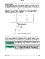
Page 112: ...4 channels of 0 5Vdc inputs with eight channels of 4 20 mA outputs 2 pole 10 ms filter on all input channels except channels 23 and 24 which have 2 pole 5 ms filter All 4 20 mA analog inputs may be us...

Page 113: ...A Isolation 500 Vrms galvanic isolation to earth ground and control common no galvanic isolation between channels Max load resistance 600 ohms load wire resistance Resolution 14 bits Accuracy Software...

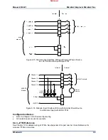
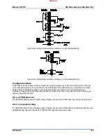
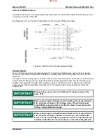
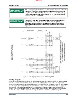
Page 114: ...n example Figure 9 7 Simplex System Configuration Example Analog Inputs For a 4 20 mA input signal the 24 8 Analog Module uses a 200 ohm resistor across the input located on the 24 8 Analog Module Eac...

Page 115: ...inputs when used with the Dataforth current input plug in module This will allow the block to use the module factory voltage calibration values with a gain factor for a 200 ohm external resistor on th...

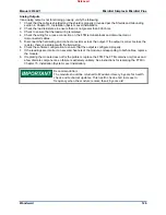
Page 116: ...ting Each 24 8 Analog Smart Plus module has a red Fault LED that is turned on when the system is reset During initialization of a module which occurs after every CPU reset the CPU turns the Fault LED...

Page 117: ...oise on the input terminals 4 Check the wiring If the inputs are reading 0 or the engineering units that correspond to 0 mA look for a loose connection on the terminal blocks disconnected or misconnec...

Page 118: ...20mA current mode All inputs have 2 pole 10ms filter except channels 11 and 12 which have 2 pole 5ms filter Note When changing a GAP selectable input type the application must be saved and an applica...

Page 119: ...poles Derivative Filter 5 10 000 ms 1 pole speed filter Acceleration Limit 1 10 000 percent second Operating Temperature 15 to 65 C Speed probe supply current 320mA total for all 4 channels Table 9 5...

Page 120: ...CMRR 200 Vdc common mode voltage rejection Read backResolution Source 12 bits Return 8 bits Read back Accuracy Source 0 5 of 0 25 mA full scale Return 1 of 0 25 mA full scale Read back temp drift 400...

Page 121: ...two handles which when toggled pushed outward move the modules out just far enough for the boards to disengage the motherboard connectors In a simplex system each Speed Analog IO Combo Smart Plus Modu...

Page 122: ...recommended that gears mounted on an auxiliary shaft coupled to the rotor be used to sense speed Auxiliary shafts tend to turn more slowly than the rotor reducing speed sensing resolution and have cou...

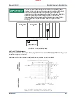
Page 123: ...prevent an inadvertent short from damaging the module The 24 Vdc outputs are capable of providing 24 Vdc with 10 regulation Power connections can be made through terminals located on the 24 8 Analog...

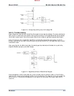
Page 124: ...ly initialized together Figure 9 13 Analog Input Wiring for a 24 8 Analog FTM Analog Outputs There are four analog output channels of 4 20 mA with a full scale range of 0 25 mA All Analog Outputs can...

Page 125: ...xecuted to average the speed values in order to improve speed sensor resolution at input frequencies greater than 200 Hz This digital filter also provides a derivative output Once every rate time 5 20...

Page 126: ...s special information At run time the CPU then periodically broadcasts a key to all I O cards telling them which rate groups are to be updated at that time Through this initialization key broadcast sy...

Page 127: ...double zero crossings 4 Verify that no ground connection exists and that the resulting 60 Hz signal is absent 5 Measure the frequency It should be in the range of 1Hz to 25 kHz 6 Check the wiring Look...

Page 128: ...nnect a resistor across the output If the output is correct across the resistor there is a problem with the field wiring 6 Check the software configuration to ensure that the output is configured prop...

Page 129: ...ings Section 9 29 added Note following 4 20mA Output Ratings Added 1 Mbps CAN Network Trunk Line Specifications to Table 6 6 Moved Section 6 3 through 6 6 information to Volume 3 Moved Section 7 2 thr...

Page 130: ...0522 1519 USA 1041 Woodward Way Fort Collins CO 80524 USA Phone 1 970 482 5811 Email and Website www woodward com Woodward has company owned plants subsidiaries and branches as well as authorized dist...

Reviews: