Manual 26166V1
MicroNet Simplex & MicroNet Plus
Woodward
58
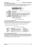
Note:
The CPU P1020 Module cannot be configured to function as a remote RTN module.
It is recommended to verify proper switch settings before installing
the module in the system and when troubleshooting CPU or RTN
related issues.
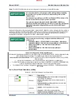
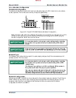
The Network Type setting on all CPU and Remote RTN modules in the
system must match for proper system operation.
The customer network attached to GbE1, GbE2, ENET1, ENET2 may
already use the RTN port addresses of 172.20.x.x. In this case, the Network
Type switch should be configured ON to use the 10.250.x.x RTN port
addresses.
Network Configuration. Ethernet ports (GbE1, GbE2, ENET1, ENET2) can be configured for the customer
network as desired. The RTN ports (RTN1, RTN2) are reserved for communicating with Woodward Real
Time Network devices such as expansion racks. See the on-site Network Administrator to define an
appropriate I/P address configuration for GbE1, GbE2, ENET1, ENET2.
This module has been factory configured with fixed Ethernet IP
addresses of
Gigabit #1 (GbE1) =
172.16.100.1
, Subnet Mask = 255.255.0.0
Gigabit #2 (GbE2) = 192.168.128.20, Subnet Mask = 255.255.255.0
Ethernet #1 (ENET1) = 192.168.129.20, Subnet Mask =
255.255.255.0
Ethernet #2 (ENET2) = 192.168.130.20, Subnet Mask =
255.255.255.0
Network Configuration Utility (AppManager)
Woodward's
AppManager
software can be used to load Control software (GAP), monitor diagnostic faults,
and configure Network settings. The
AppManager
utility can be downloaded from
www.woodward.com/ic/software.
A PC connection must be made to Gigabit #1 (GbE1) using a RJ45
Ethernet cable.
Locate the ControlName on the module faceplate and highlight it in
AppManager
.
To VIEW the IP address configuration, select menu option CONTROL - CONTROL INFORMATION.
Look for the Ethernet adapter addresses under the Footprint Description.
To CHANGE the IP address configuration, select menu option CONTROL - CHANGE NETWORK
SETTINGS.
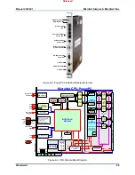
6.2.3—Front Panel Indicators (LEDs)
Table 6-1. CPU P1020 Module Front Panel LEDs
LED Name
Description
Ethernet
Blinking GREEN when link and data is transmitted
or received at 100 Mbps.
Blilnking YELLOW when link and data transfer is
10 Mbps
Blinking GREEN and YELLOW when link and data
transfer is 1000 Mbps
STATUS
GREEN – GAP application is running
YELLOW – CPU OS is running and idle.
SYSCON
System Controller (GREEN)—Active when this
CPU module is the VMEbus System Controller.
Released

