Manual 26166V1
MicroNet Simplex & MicroNet Plus
Woodward
68
6.3.5—10/100 BaseT Ethernet Ports
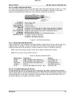
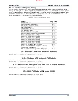
There are two 10/100 BaseT Ethernet Ports (RJ45) available to the application software. These ports are
full duplex, auto switching, and do not require the use of an Ethernet shield box.
Max cable length is 30 meters. Double shielded, Cat 5 Ethernet cables
(SSTP) are required for customer installations.
6.3.6—RTN Ports
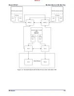
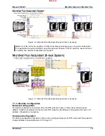
Two Real Time Network ports (RJ45) are available to provide communications between the main chassis
CPU's and any Remote RTN modules located in an expansion chassis. The GAP software application
defines the expansion racks, their I/O modules, and the use of these RTN ports (GAP block is RTN).
For redundant systems, up to (2) Remote RTN modules may be installed into each expansion chassis.
When initialized by the main chassis CPU, the Remote RTN modules will acquire either a SYSCON or
STANDBY status. The Remote RTN module that becomes SYSCON will control the expansion chassis it
is located in. It will synchronize with the STANDBY Remote RTN module and perform any redundancy
functions as necessary. Input and output data from all I/O modules will be managed appropriately and
made available to the GAP Application running in the main-chassis CPUs.
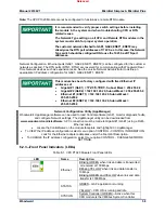
Double shielded, Cat 5 Ethernet cables (SSTP) are required for
customer installations.
Cable length between the Main rack and RTN switch is 3 m (10 ft.)
max.
Cable length between the RTN switch and Expansion rack is 30 m
(100 ft.) max.
6.3.7—RS-232/422/485 Serial Port
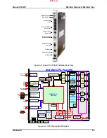
An isolated, configurable RS-232 / 422 / 485 serial port is located on the front of the CPU module and is
configured by the GAP software application. The baud rate is selectable from 300 Bd to 57.6 kBd.
Shielded cable is required when connecting to the CPU module’s serial port. Using shielded cable will
help ensure the robustness of the serial communications.
When using RTU serial protocols, only a single MicroNet slave is
supported—no multi-drop.
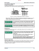
Pin 1 – RS-422 Transmit (+)
Pin 2 – RS-232 Receive
Pin 3 – RS-232 Transmit
Pin 4 – RS-422 Transmit (-)
Pin 5 – Signal Ground
Pin 6 – Termination Resistor (+)
Pin 7 – RS-485/422 Receive (+)
Pin 8 – RS-485/422 Receive (-)
Pin 9 – Termination Resistor (-)
Figure 6-11. CPU Communications Port (DB9F)
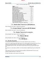
6.3.8—RS-232 Service Port
An isolated RS-232 service port is located on the front of the CPU module. This port is for VxWorks
operating system use only and cannot be configured for application software use. The communication
settings are fixed at 38.4 kBd, 8 data bits, no parity, 1 stop-bit, and no flow control.
For debug use, a null-modem cable and 5450-1065 Serial Adapter cable (PS2M to DB9F) is required to
attach this port to a PC. This port is to be used by trained Field Service personnel only!
Released


